DISASSEMBLY INSTRUCTIONS
1.REMOVAL OF MECHANICAL PARTS AND P.C. BOARDS
CAUTION
Be careful not to remove the FFC cable forcibly, because the FFC cable may be damaged.
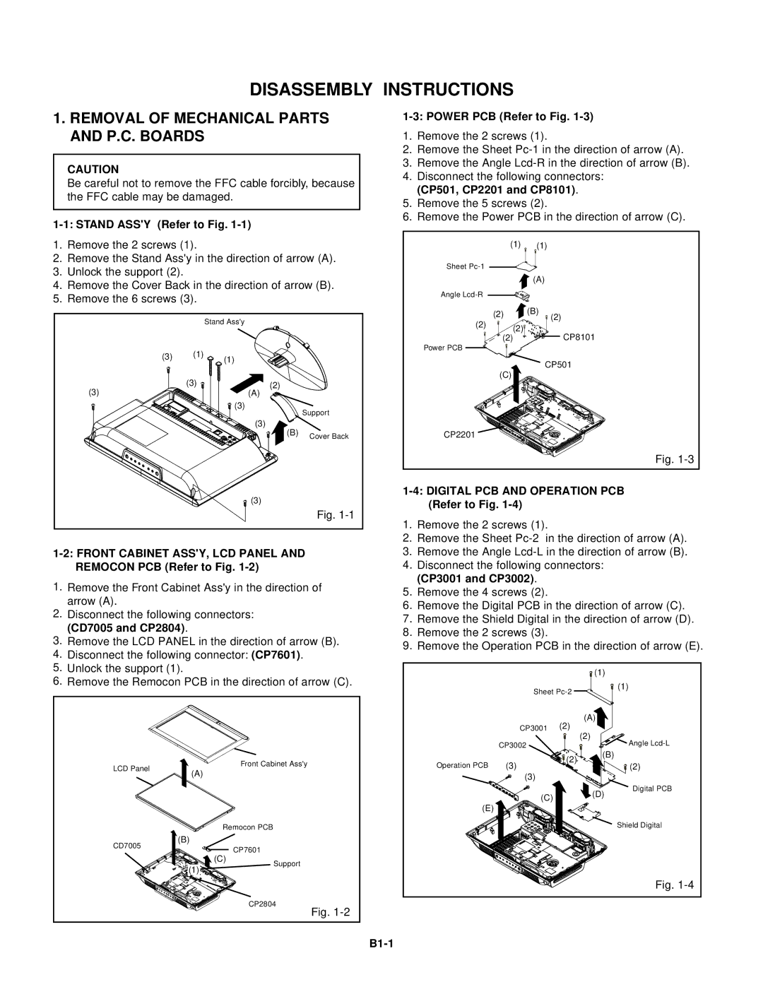
1-1: STAND ASS'Y (Refer to Fig. 1-1)
1.Remove the 2 screws (1).
2.Remove the Stand Ass'y in the direction of arrow (A).
3.Unlock the support (2).
4.Remove the Cover Back in the direction of arrow (B).
5.Remove the 6 screws (3).
|
| Stand Ass'y |
|
(3) | (1) | (1) |
|
|
|
| |
(3) | (3) | (2) |
|
| (A) |
| |
|
| (3) | Support |
|
|
| |
|
| (3) |
|
|
| (B) | Cover Back |
|
|
| |
|
| (3) |
|
|
|
| Fig. |
1-2: FRONT CABINET ASS'Y, LCD PANEL AND REMOCON PCB (Refer to Fig. 1-2)
1.Remove the Front Cabinet Ass'y in the direction of arrow (A).
2.Disconnect the following connectors: (CD7005 and CP2804).
3.Remove the LCD PANEL in the direction of arrow (B).
4.Disconnect the following connector: (CP7601).
5.Unlock the support (1).
6.Remove the Remocon PCB in the direction of arrow (C).
LCD Panel |
| Front Cabinet Ass'y |
(A) |
| |
|
| |
| Remocon PCB | |
CD7005 | (B) |
|
| CP7601 | |
| (C) | |
| Support | |
| (1) | |
|
| |
|
| CP2804 |
|
| Fig. |
1-3: POWER PCB (Refer to Fig. 1-3)
1.Remove the 2 screws (1).
2.Remove the Sheet
3.Remove the Angle
4.Disconnect the following connectors: (CP501, CP2201 and CP8101).
5.Remove the 5 screws (2).
6.Remove the Power PCB in the direction of arrow (C).
| (1) | (1) |
Sheet |
|
|
|
| (A) |
Angle |
|
|
| (2) | (B) |
| (2) | |
(2) |
| |
(2) |
| |
| CP8101 | |
| (2) | |
Power PCB |
|
|
|
| CP501 |
| (C) |
|
CP2201 |
|
|
|
| Fig. |
1-4: DIGITAL PCB AND OPERATION PCB (Refer to Fig. 1-4)
1.Remove the 2 screws (1).
2.Remove the Sheet
3.Remove the Angle
4.Disconnect the following connectors: (CP3001 and CP3002).
5.Remove the 4 screws (2).
6.Remove the Digital PCB in the direction of arrow (C).
7.Remove the Shield Digital in the direction of arrow (D).
8.Remove the 2 screws (3).
9.Remove the Operation PCB in the direction of arrow (E).
|
|
| (1) | |
| Sheet | (1) | ||
|
| |||
|
| (2) | (A) | |
| CP3001 | (2) | ||
|
|
| ||
| CP3002 |
| Angle | |
|
| (2) | (B) | |
Operation PCB | (3) | (2) | ||
| ||||
| (3) |
|
| |
|
|
| Digital PCB | |
| (C) |
| (D) | |
|
|
| ||
(E) |
|
|
| |
|
|
| Shield Digital | |
|
|
| Fig. | |