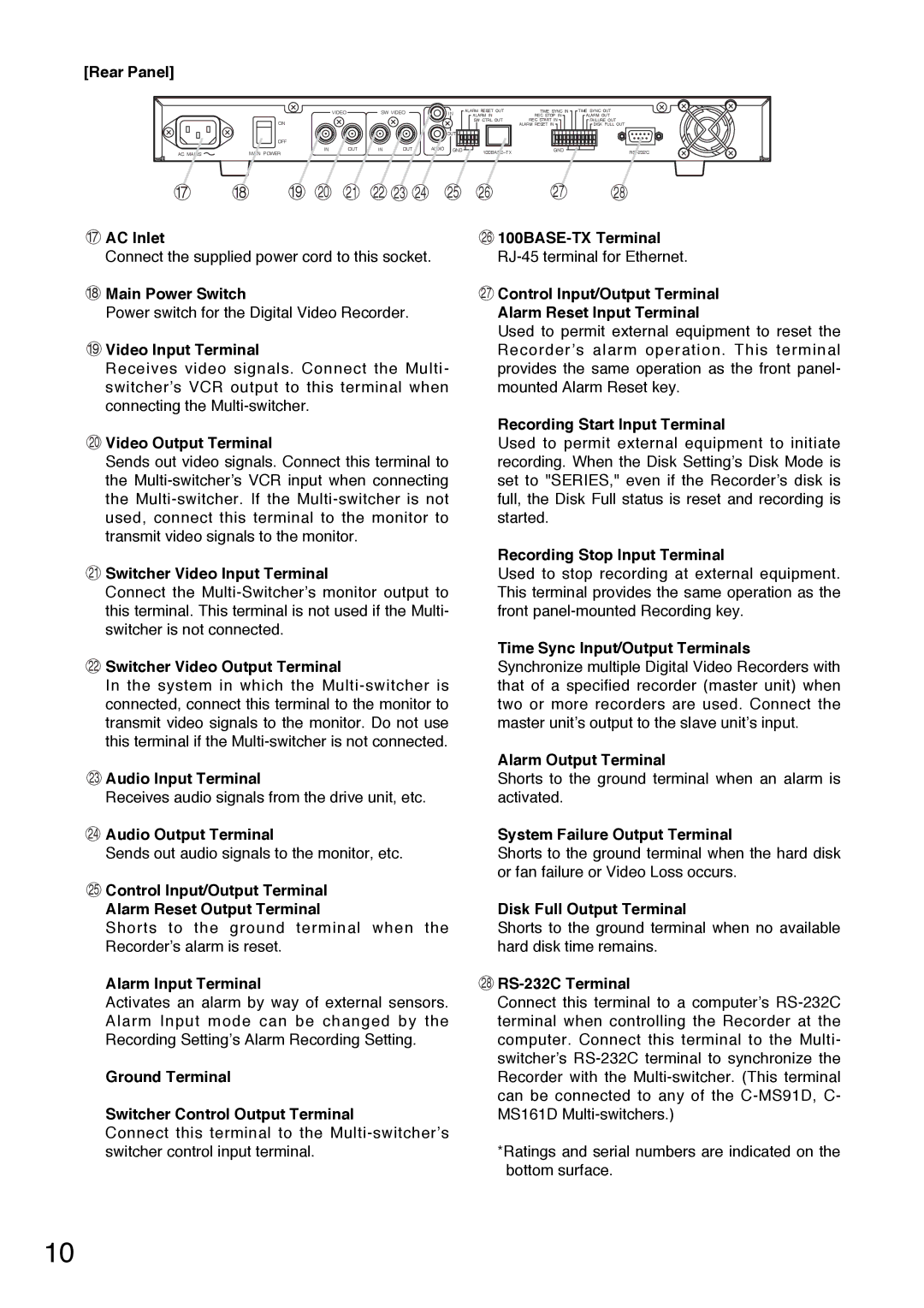
[Rear Panel]


VIDEO

SW VIDEO

IN

ALARM RESET OUT

TIME SYNC IN

TIME SYNC OUT


ALARM IN

REC STOP IN

ALARM OUT


ON


SW CTRL OUT

REC START IN

FAILURE OUT


ALARM RESET IN

DISK FULL OUT


OUT


OFF


AC MAINS

IN

OUT

IN

OUT

AUDIO GND

100BASE–TX

GND

RS–232C

MAIN POWER


17

18

19

20

21

22

23

24

25

26

27

28

17AC Inlet

Connect the supplied power cord to this socket.

18Main Power Switch

Power switch for the Digital Video Recorder.

19Video Input Terminal

Receives video signals. Connect the Multi- switcher’s VCR output to this terminal when connecting the Multi-switcher.

26100BASE-TX Terminal RJ-45 terminal for Ethernet.

27Control Input/Output Terminal Alarm Reset Input Terminal

Used to permit external equipment to reset the Recorder’s alarm operation. This terminal provides the same operation as the front panel- mounted Alarm Reset key.

Recording Start Input Terminal

20Video Output Terminal

Sends out video signals. Connect this terminal to the Multi-switcher’s VCR input when connecting the Multi-switcher. If the Multi-switcher is not used, connect this terminal to the monitor to transmit video signals to the monitor.

Used to permit external equipment to initiate recording. When the Disk Setting’s Disk Mode is set to "SERIES," even if the Recorder’s disk is full, the Disk Full status is reset and recording is started.

Recording Stop Input Terminal

21Switcher Video Input Terminal

Connect the Multi-Switcher’s monitor output to this terminal. This terminal is not used if the Multi- switcher is not connected.

Used to stop recording at external equipment. This terminal provides the same operation as the front panel-mounted Recording key.

Time Sync Input/Output Terminals

22Switcher Video Output Terminal

In the system in which the Multi-switcher is connected, connect this terminal to the monitor to transmit video signals to the monitor. Do not use this terminal if the Multi-switcher is not connected.

23Audio Input Terminal

Receives audio signals from the drive unit, etc.

24Audio Output Terminal

Sends out audio signals to the monitor, etc.

25Control Input/Output Terminal Alarm Reset Output Terminal

Shorts to the ground terminal when the Recorder’s alarm is reset.

Alarm Input Terminal

Activates an alarm by way of external sensors. Alarm Input mode can be changed by the Recording Setting’s Alarm Recording Setting.

Ground Terminal

Switcher Control Output Terminal

Connect this terminal to the Multi-switcher’s switcher control input terminal.

Synchronize multiple Digital Video Recorders with that of a specified recorder (master unit) when two or more recorders are used. Connect the master unit’s output to the slave unit’s input.

Alarm Output Terminal

Shorts to the ground terminal when an alarm is activated.

System Failure Output Terminal

Shorts to the ground terminal when the hard disk or fan failure or Video Loss occurs.

Disk Full Output Terminal

Shorts to the ground terminal when no available hard disk time remains.

28RS-232C Terminal

Connect this terminal to a computer’s RS-232C terminal when controlling the Recorder at the computer. Connect this terminal to the Multi- switcher’s RS-232C terminal to synchronize the Recorder with the Multi-switcher. (This terminal can be connected to any of the C-MS91D, C- MS161D Multi-switchers.)

*Ratings and serial numbers are indicated on the bottom surface.

10

Page 10
Image 10
Toshiba C-DR0101 Rear Panel, AC Inlet, Main Power Switch, Video Input Terminal, Audio Input Terminal, Alarm Input Terminal

C-DR0101 specifications

The Toshiba C-DR0101 is an innovative digital radiography (DR) system designed to enhance imaging capabilities in medical facilities. This advanced system combines Toshiba's cutting-edge technology with user-friendly features to improve diagnostic efficiency and patient care.

One of the standout features of the C-DR0101 is its proprietary flat-panel detector, which provides high-resolution images with exceptional detail. This detector offers a wide dynamic range, maximizing the quality of images captured in various clinical situations, from routine examinations to complex procedures. The system is equipped with advanced image processing algorithms that enhance image clarity and reduce noise, ensuring that healthcare professionals have access to accurate diagnostics.

The C-DR0101 is designed with ease of use in mind. Its intuitive user interface streamlines workflow, allowing radiologists and technicians to quickly select imaging protocols and adjust settings as needed. This user-friendly design not only saves time but also minimizes the learning curve for new operators. The system's compact footprint allows for easy integration into existing radiology departments, making it a versatile choice for various healthcare environments.

In terms of technology, the C-DR0101 utilizes wireless connectivity, which allows for more flexible positioning of the detector and reduces clutter in the exam room. This wireless feature also facilitates the seamless transfer of images to the hospital's information system, enabling quick access to patient data and images for timely decision-making.

Another key characteristic of the C-DR0101 is its enhanced patient safety features. The system is designed to minimize radiation exposure while still delivering high-quality images. This is achieved through advanced dose management technologies and customizable exposure settings tailored to the specific needs of each patient. This focus on patient safety aligns with the goals of modern healthcare to prioritize the well-being of patients while delivering effective diagnostic imaging solutions.

The Toshiba C-DR0101 stands out in the field of digital radiography through its combination of advanced imaging technology, user-friendly design, and commitment to patient safety. As healthcare continues to evolve, systems like the C-DR0101 play a crucial role in ensuring that medical professionals can provide prompt and accurate care.