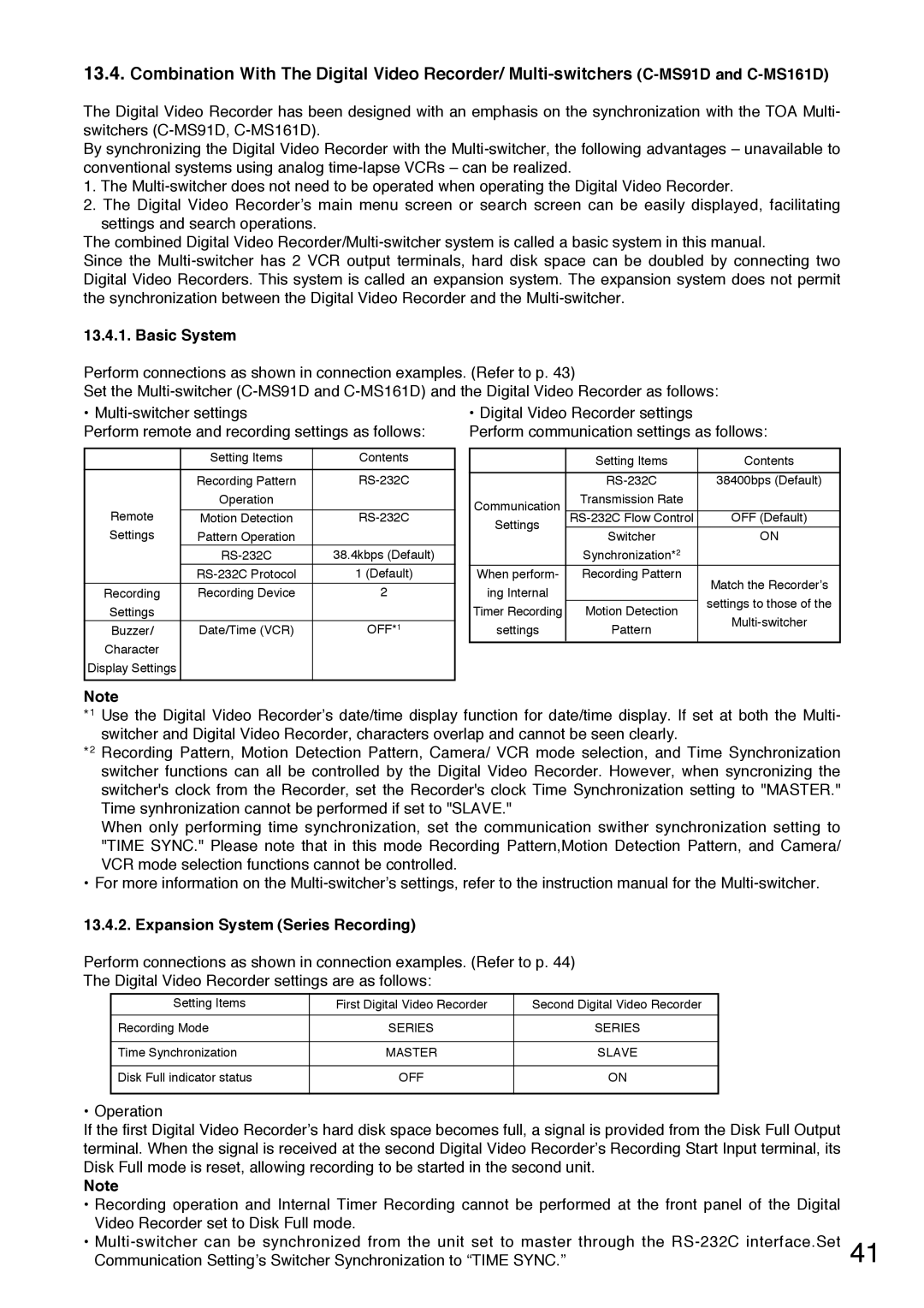
C-DR0101 specifications
The Toshiba C-DR0101 is an innovative digital radiography (DR) system designed to enhance imaging capabilities in medical facilities. This advanced system combines Toshiba's cutting-edge technology with user-friendly features to improve diagnostic efficiency and patient care.One of the standout features of the C-DR0101 is its proprietary flat-panel detector, which provides high-resolution images with exceptional detail. This detector offers a wide dynamic range, maximizing the quality of images captured in various clinical situations, from routine examinations to complex procedures. The system is equipped with advanced image processing algorithms that enhance image clarity and reduce noise, ensuring that healthcare professionals have access to accurate diagnostics.
The C-DR0101 is designed with ease of use in mind. Its intuitive user interface streamlines workflow, allowing radiologists and technicians to quickly select imaging protocols and adjust settings as needed. This user-friendly design not only saves time but also minimizes the learning curve for new operators. The system's compact footprint allows for easy integration into existing radiology departments, making it a versatile choice for various healthcare environments.
In terms of technology, the C-DR0101 utilizes wireless connectivity, which allows for more flexible positioning of the detector and reduces clutter in the exam room. This wireless feature also facilitates the seamless transfer of images to the hospital's information system, enabling quick access to patient data and images for timely decision-making.
Another key characteristic of the C-DR0101 is its enhanced patient safety features. The system is designed to minimize radiation exposure while still delivering high-quality images. This is achieved through advanced dose management technologies and customizable exposure settings tailored to the specific needs of each patient. This focus on patient safety aligns with the goals of modern healthcare to prioritize the well-being of patients while delivering effective diagnostic imaging solutions.
The Toshiba C-DR0101 stands out in the field of digital radiography through its combination of advanced imaging technology, user-friendly design, and commitment to patient safety. As healthcare continues to evolve, systems like the C-DR0101 play a crucial role in ensuring that medical professionals can provide prompt and accurate care.
