E6580772③
2.2 Wiring
When conduct wiring, follow the instructions below.
•Use shield wire for control signal line and ground the unit with shield wire.
•Applicable wire size for TB1 is 0.2 to 2.5mm2.
For TB2, it is 0.2 to 1.5mm2.
•Peel off the end of the wire by about 5mm (7mm for TB1).
•For connecting wires, use screwdriver that has a blade tip of 0.4mm thickness and 2.5mm width. (For TB3, thickness and width should be 0.6mm and 3.5mm.)
•Tightening torque of the terminal block should be 0.22 to 0.25N・m .
(For TB1, it is 0.5 to 0.6N・m.)
•Never bind the signal line and main circuit connection wire together.
Separate the signal line and the main circuit connection wire by more than 200mm.
•Use 0.75mm2 wire for the connection of PGCC terminal of the option side and CC terminal of the inverter.
•Use 0.75mm2 wire for the connection of grounding terminal of the option side and that of the inverter.
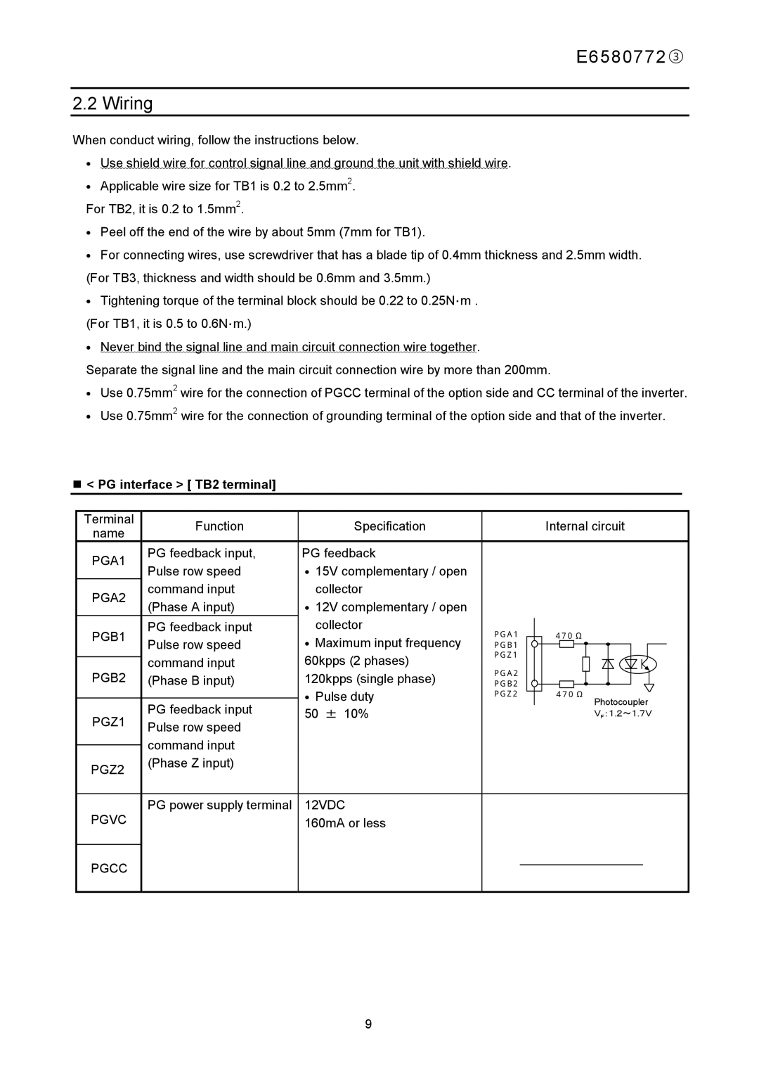
< PG interface > [ TB2 terminal]
Terminal | Function | Specification |
|
|
|
| Internal circuit | ||||||
name |
|
|
|
| |||||||||
|
|
|
|
|
|
|
|
|
|
|
|
| |
PGA1 | PG feedback input, | PG feedback |
|
|
|
|
|
|
|
|
|
|
|
Pulse row speed | • 15V complementary / open |
|
|
|
|
|
|
|
|
|
|
| |
|
|
|
|
|
|
|
|
|
|
|
| ||
PGA2 | command input | collector |
|
|
|
|
|
|
|
|
|
|
|
(Phase A input) | • 12V complementary / open |
|
|
|
|
|
|
|
|
|
|
| |
|
|
|
|
|
|
|
|
|
|
|
| ||
PGB1 | PG feedback input | collector | PGA1 |
|
| 470 Ω |
|
|
| ||||
Pulse row speed | • Maximum input frequency |
|
|
|
|
| |||||||
| PGB1 |
|
|
|
|
|
|
|
|
| |||
| command input | 60kpps (2 phases) | PGZ1 |
|
|
|
|
|
|
|
|
| |
|
|
|
|
|
|
|
|
|
| ||||
PGB2 | PGA2 |
|
|
|
|
|
|
|
|
| |||
(Phase B input) | 120kpps (single phase) |
|
|
|
|
|
|
|
|
| |||
PGB2 |
|
|
|
|
|
|
|
|
| ||||
|
|
|
|
|
|
|
|
| |||||
|
| • Pulse duty | PGZ2 |
|
| 470 Ω |
|
|
| ||||
|
|
|
|
|
|
| |||||||
|
|
|
|
| |||||||||
| PG feedback input | 50 ± 10% |
|
|
|
|
|
|
| Photocoupler | |||
PGZ1 |
|
|
|
|
|
|
| V | :1.2~1.7V | ||||
Pulse row speed |
|
|
|
|
|
|
| F |
|
|
| ||
|
|
|
|
|
|
|
|
|
|
|
| ||
|
|
|
|
|
|
|
|
|
|
|
|
| |
| command input |
|
|
|
|
|
|
|
|
|
|
|
|
|
|
|
|
|
|
|
|
|
|
|
|
| |
PGZ2 | (Phase Z input) |
|
|
|
|
|
|
|
|
|
|
|
|
|
|
|
|
|
|
|
|
|
|
|
|
| |
|
|
|
|
|
|
|
|
|
|
|
|
|
|
PGVC | PG power supply terminal | 12VDC |
|
|
|
|
|
|
|
|
|
|
|
| 160mA or less |
|
|
|
|
|
|
|
|
|
|
| |
|
|
|
|
|
|
|
|
|
|
|
|
|
|
PGCC |
|
|
|
|
|
|
|
|
|
|
|
|
|
|
|
|
|
|
|
|
|
|
|
|
|
| |
|
|
|
|
|
|
|
|
|
|
|
|
|
|
9