E6580772③
3.2.4 Vector control setting parameter
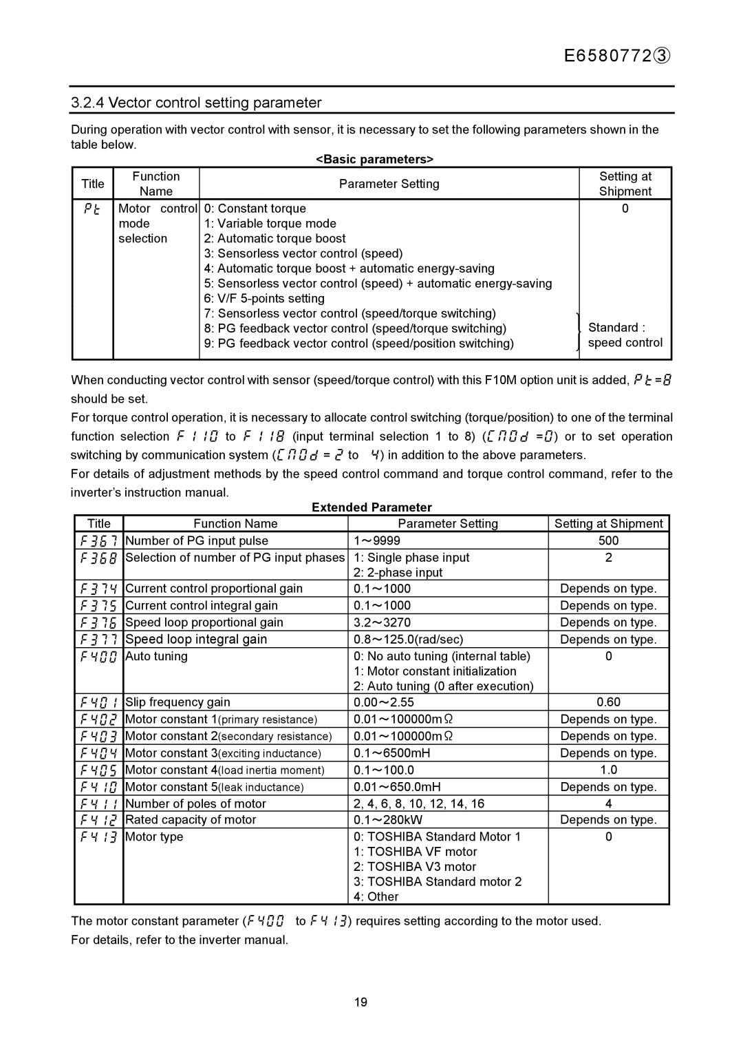
During operation with vector control with sensor, it is necessary to set the following parameters shown in the table below.
|
|
| <Basic parameters> |
|
Title | Function |
| Parameter Setting | Setting at |
Name |
| Shipment | ||
|
|
| ||
pt | Motor control | 0: | Constant torque | 0 |
| mode | 1: | Variable torque mode |
|
| selection | 2: | Automatic torque boost |
|
|
| 3: | Sensorless vector control (speed) |
|
|
| 4: | Automatic torque boost + automatic |
|
|
| 5: | Sensorless vector control (speed) + automatic |
|
|
| 6: | V/F |
|
|
| 7: | Sensorless vector control (speed/torque switching) | Standard : |
|
| 8: | PG feedback vector control (speed/torque switching) | |
|
| 9: | PG feedback vector control (speed/position switching) | speed control |
|
|
|
|
|
When conducting vector control with sensor (speed/torque control) with this F10M option unit is added, pt=8 should be set.
For torque control operation, it is necessary to allocate control switching (torque/position) to one of the terminal function selection f110 to f118 (input terminal selection 1 to 8) (cmod =0) or to set operation switching by communication system (cmod = 2 to 4) in addition to the above parameters.
For details of adjustment methods by the speed control command and torque control command, refer to the inverter’s instruction manual.
Extended Parameter
Title | Function Name | Parameter Setting | Setting at Shipment |
f367 | Number of PG input pulse | 1~9999 | 500 |
f368 | Selection of number of PG input phases | 1: Single phase input | 2 |
|
| 2: |
|
f374 | Current control proportional gain | 0.1~1000 | Depends on type. |
f375 | Current control integral gain | 0.1~1000 | Depends on type. |
f376 | Speed loop proportional gain | 3.2~3270 | Depends on type. |
f377 | Speed loop integral gain | 0.8~125.0(rad/sec) | Depends on type. |
f400 | Auto tuning | 0: No auto tuning (internal table) | 0 |
|
| 1: Motor constant initialization |
|
|
| 2: Auto tuning (0 after execution) |
|
f401 | Slip frequency gain | 0.00~2.55 | 0.60 |
f402 | Motor constant 1(primary resistance) | 0.01~100000mΩ | Depends on type. |
f403 | Motor constant 2(secondary resistance) | 0.01~100000mΩ | Depends on type. |
f404 | Motor constant 3(exciting inductance) | 0.1~6500mH | Depends on type. |
f405 | Motor constant 4(load inertia moment) | 0.1~100.0 | 1.0 |
f410 | Motor constant 5(leak inductance) | 0.01~650.0mH | Depends on type. |
f411 | Number of poles of motor | 2, 4, 6, 8, 10, 12, 14, 16 | 4 |
f412 | Rated capacity of motor | 0.1~280kW | Depends on type. |
f413 | Motor type | 0: TOSHIBA Standard Motor 1 | 0 |
|
| 1: TOSHIBA VF motor |
|
|
| 2: TOSHIBA V3 motor |
|
|
| 3: TOSHIBA Standard motor 2 |
|
|
| 4: Other |
|
The motor constant parameter (f400 to f413) requires setting according to the motor used. For details, refer to the inverter manual.
19
