E6580772③
★Caution in case of using open collector encoder connection
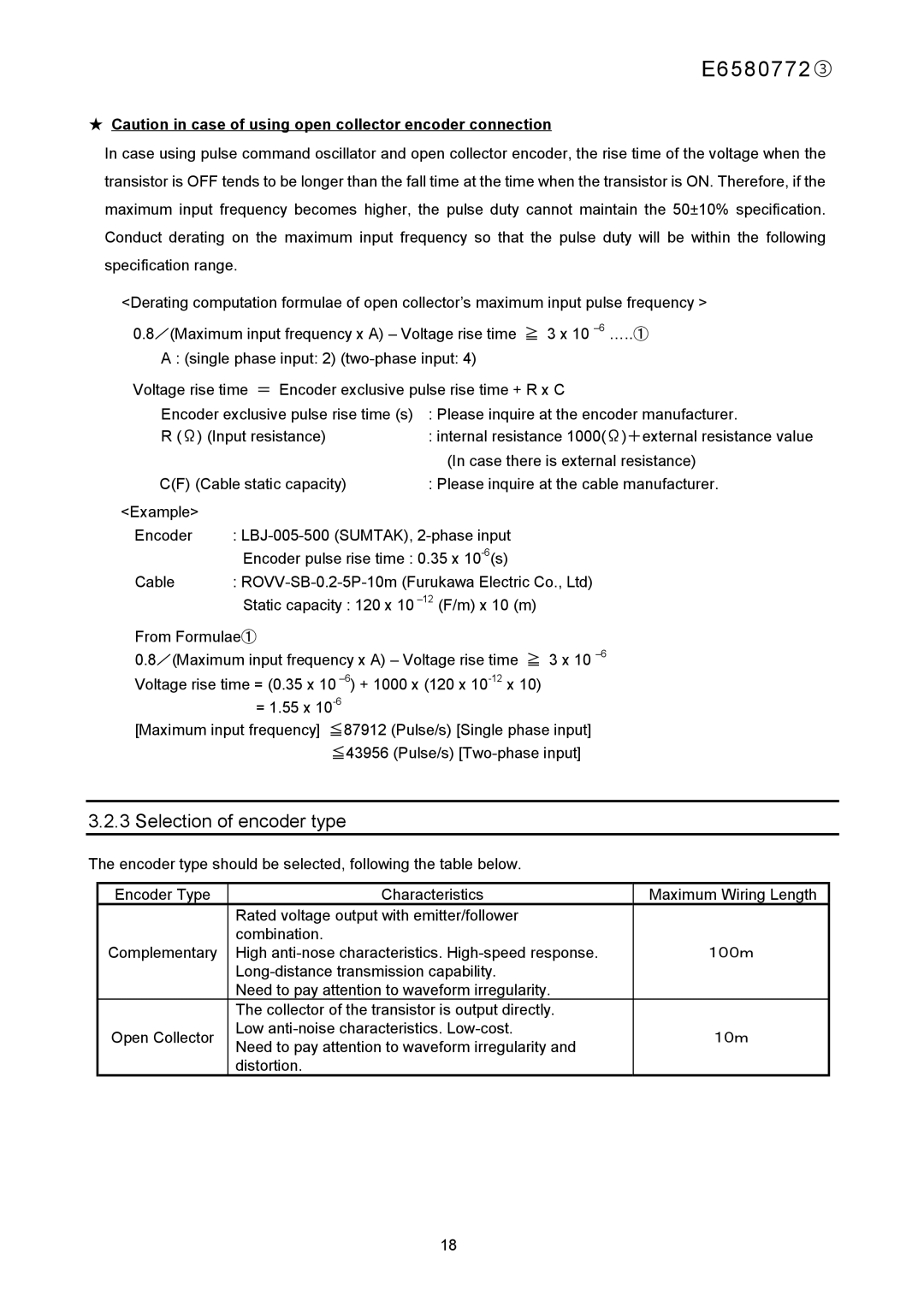
In case using pulse command oscillator and open collector encoder, the rise time of the voltage when the transistor is OFF tends to be longer than the fall time at the time when the transistor is ON. Therefore, if the maximum input frequency becomes higher, the pulse duty cannot maintain the 50±10% specification. Conduct derating on the maximum input frequency so that the pulse duty will be within the following specification range.
<Derating computation formulae of open collector’s maximum input pulse frequency >
0.8/(Maximum input frequency x A) – Voltage rise time ≧ 3 x 10
A : (single phase input: 2)
Voltage rise time = Encoder exclusive pulse rise time + R x C
Encoder exclusive pulse rise time (s) : Please inquire at the encoder manufacturer.
R (Ω) (Input resistance) | : internal resistance 1000(Ω)+external resistance value | |
|
| (In case there is external resistance) |
C(F) (Cable static capacity) | : Please inquire at the cable manufacturer. | |
<Example> |
|
|
Encoder | : | |
| Encoder pulse rise time : 0.35 x | |
Cable | : | |
| Static capacity : 120 x 10 | |
From Formulae①
0.8/(Maximum input frequency x A) – Voltage rise time ≧ 3 x 10
= 1.55 x
[Maximum input frequency] ≦87912 (Pulse/s) [Single phase input] ≦43956 (Pulse/s)
3.2.3 Selection of encoder type
The encoder type should be selected, following the table below.
Encoder Type | Characteristics | Maximum Wiring Length | |
| Rated voltage output with emitter/follower |
| |
| combination. |
| |
Complementary | High | 100m | |
|
| ||
| Need to pay attention to waveform irregularity. |
| |
| The collector of the transistor is output directly. |
| |
Open Collector | Low | 10m | |
Need to pay attention to waveform irregularity and | |||
|
| ||
| distortion. |
|
18
