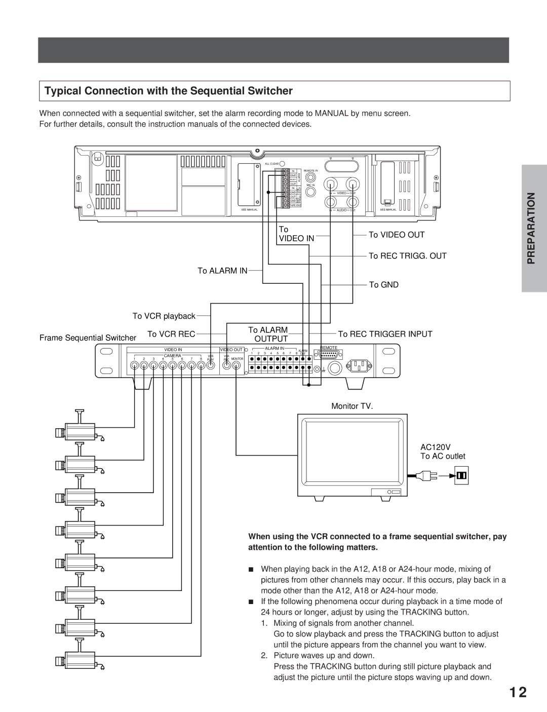
Typical Connection with the Sequential Switcher
When connected with a sequential switcher, set the alarm recording mode to MANUAL by menu screen. For further details, consult the instruction manuals of the connected devices.
ALL CLEAR |
|
|
|
|
|
IN | ALARM | REMOTE IN |
|
|
|
GND |
|
|
|
| |
RESET |
|
|
|
|
|
OUT |
| MIC IN |
|
|
|
GND | ONE SHOT |
|
|
| |
IN |
|
|
|
|
|
GND | . | IN | VIDEO | OUT |
|
REC TRIGG |
|
|
|
| |
OUT |
|
|
|
|
|
TAPE END |
|
|
|
| |
SEE MANUAL |
| IN | AUDIO | OUT | SEE MANUAL |
To |
| To VIDEO OUT | ||||
|
|
|
|
|
| |
VIDEO IN |
| |||||
|
| |||||
|
|
|
|
|
| To REC TRIGG. OUT |
|
|
|
|
|
| |
To ALARM IN
To GND
To VCR playback |
|
|
|
|
|
|
|
|
| |
|
|
|
|
|
|
|
| |||
Frame Sequential Switcher | To VCR REC |
|
|
| To ALARM |
|
|
|
| To REC TRIGGER INPUT |
|
| OUTPUT |
| |||||||
|
|
|
|
|
| |||||
|
|
|
| VIDEO IN |
|
|
| VIDEO OUT |
| ALARM IN |
|
| REMOTE | |||||
|
|
|
|
|
|
|
|
|
|
|
|
|
| ALARM | ||||
|
|
|
| CAMERA |
|
|
| VCR | VCR | 1 | 2 | 3 | 4 | 5 | 6 | 7 | 8 | OUT |
|
|
|
|
|
|
| MONITOR |
|
|
|
|
|
|
|
| |||
1 | 2 | 3 | 4 | 5 | 6 | 7 | 8 | PLAY | REC |
|
|
|
|
|
|
|
| |
|
|
|
|
|
|
|
|
|
|
|
|
|
|
|
|
|
| Monitor TV. |
|
|
|
|
|
|
|
|
|
|
|
|
|
|
|
|
|
| AC120V |
|
|
|
|
|
|
|
|
|
|
|
|
|
|
|
|
|
| To AC outlet |
When using the VCR connected to a frame sequential switcher, pay attention to the following matters.
iWhen playing back in the A12, A18 or
iIf the following phenomena occur during playback in a time mode of
24hours or longer, adjust by using the TRACKING button.
1.Mixing of signals from another channel.
Go to slow playback and press the TRACKING button to adjust until the picture appears from the channel you want to view.
2.Picture waves up and down.
Press the TRACKING button during still picture playback and
adjust the picture until the picture stops waving up and down.
INTRODUCTION
PREPARATION
RECORDING | OPERATION |
PLAYBACK | OPERATION |
NOTICE
12
