INTRODUCTION
Rear Panel
PREPARATION
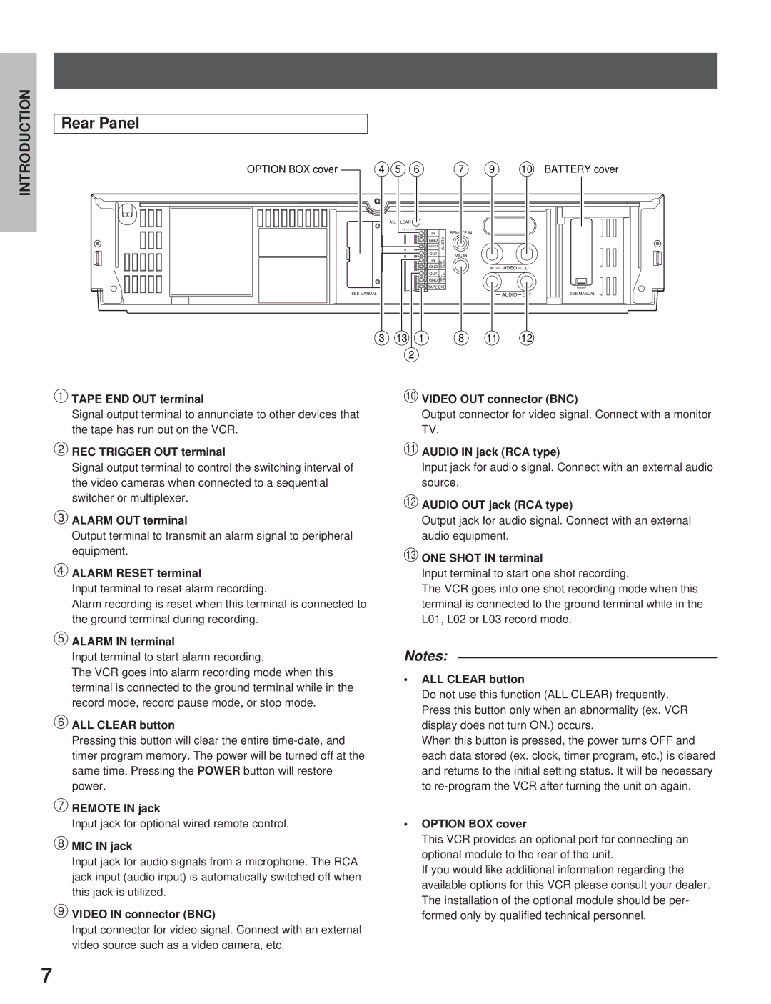
OPTION BOX cover | 4 | 5 | 6 |
|
| ALL CLEAR |
|
|
|
| IN |
GND | ALARM |
RESET |
|
|
|
OUT |
|
GND | ONE SHOT |
IN |
|
|
|
GND | . |
REC TRIGG | |
OUT |
|
TAPE END
SEE MANUAL
3 | 13 | 1 |
2
7 | 9 | 10 BATTERY cover |
REMOTE IN
MIC IN
IN VIDEO OUT
AUDIO | SEE MANUAL |
8 11 12
RECORDING | OPERATION |
|
|
PLAYBACK | OPERATION |
|
|
NOTICE
1TAPE END OUT terminal
Signal output terminal to annunciate to other devices that the tape has run out on the VCR.
2REC TRIGGER OUT terminal
Signal output terminal to control the switching interval of the video cameras when connected to a sequential switcher or multiplexer.
3ALARM OUT terminal
Output terminal to transmit an alarm signal to peripheral equipment.
4ALARM RESET terminal
Input terminal to reset alarm recording.
Alarm recording is reset when this terminal is connected to the ground terminal during recording.
5ALARM IN terminal
Input terminal to start alarm recording.
The VCR goes into alarm recording mode when this terminal is connected to the ground terminal while in the record mode, record pause mode, or stop mode.
6ALL CLEAR button
Pressing this button will clear the entire
7REMOTE IN jack
Input jack for optional wired remote control.
8MIC IN jack
Input jack for audio signals from a microphone. The RCA jack input (audio input) is automatically switched off when this jack is utilized.
9VIDEO IN connector (BNC)
Input connector for video signal. Connect with an external video source such as a video camera, etc.
pVIDEO OUT connector (BNC)
Output connector for video signal. Connect with a monitor TV.
qAUDIO IN jack (RCA type)
Input jack for audio signal. Connect with an external audio source.
wAUDIO OUT jack (RCA type)
Output jack for audio signal. Connect with an external audio equipment.
eONE SHOT IN terminal
Input terminal to start one shot recording.
The VCR goes into one shot recording mode when this terminal is connected to the ground terminal while in the L01, L02 or L03 record mode.
Notes:
•ALL CLEAR button
Do not use this function (ALL CLEAR) frequently. Press this button only when an abnormality (ex. VCR display does not turn ON.) occurs.
When this button is pressed, the power turns OFF and each data stored (ex. clock, timer program, etc.) is cleared and returns to the initial setting status. It will be necessary to
•OPTION BOX cover
This VCR provides an optional port for connecting an optional module to the rear of the unit.
If you would like additional information regarding the available options for this VCR please consult your dealer. The installation of the optional module should be per- formed only by qualified technical personnel.
7