Manuals
/
Toshiba
/
Lawn and Garden
/
Metal Detector
Toshiba
LF414
manual
Installation Procedure, - 27 -, 6F8A0870
Models:
LF414
1
28
65
65
Download
65 pages
63.14 Kb
25
26
27
28
29
30
31
32
Troubleshooting
Specs
Install
Explanation of signal words
Wiring
Dimension
Maintenance
Zero Adjustment
About Safety Precautions
„ Turn off mains power before
Page 28
Image 28
Page 27
Page 29
Page 28
Image 28
Page 27
Page 29
Contents
6F8A0870
6F8A0870
- 1 -
About Safety Precautions
Integral type LF414/LF600F, LF414/LF610F, LF414/LF620F
SAFETY PRECAUTIONS
Explanation of signal words
Safety symbols
- 2 -
SAFETY PRECAUTIONS Safety Precautions for Installation and Wiring
- 3 -
DON’T
„ Do not modify or disassemble the enclosure
SAFETY PRECAUTIONS continued
Safety Precautions for Installation and Wiring
DON’T
- 4 -
Safety Precautions for Maintenance and Inspection
Warranty and Limitation of Liability
Usage limitation
- 5 -
Handling Precautions
- 6 -
・Places where excessive vibration or mechanical shock occurs
2 Wire cables correctly and securely
Handling Precautions continued
- 7 -
Table of Contents
- 8 -
1. Product Inspection and Storage
1.1 Product Inspection
1.2 Strage
- 9 -
Features
2. Overview
- 10 -
5 Intelligent functions
3. Names of Parts
3.1 Appearance
3.1.1 Appearance of LF414/LF600F, LF414/LF610F
Integral 1 Meter size of 1/2 inch 15mm
2 Meter size of 1inch 25mm
- 12 -
Figure 3.1.2 Appearance of LF414/LF600F, LF610F Meter size 1 inch25mm
Ground terminal for converter
3 Meter size of 1 1/2 to 4 inch 40 to 100mm
- 13 -
Figure 3.1.3 Appearance of LF414/LF600F, LF610F
Meter size 1 1/2 to 4 inch 40 to 100mm
4 Meter size of 6 and 8 inch 150 and 200mm
- 14 -
Lifting Lugs
provided
3.1.2 Appearance of LF414/LF620F
- 15 -
Figure 3.1.5 Appearance of LF414/LF620F Meter size 1/2inch15mm
Ground terminal for converter Flow direction arrow Detector
Figure 3.1.6 Appearance of LF414/LF620F Meter size 1 inch25mm
- 16 -
Ground terminal for converter Flow direction arrow
- 17 -
Figure 3.1.7 Appearance of LF414/LF620F
- 18 -
Figure 3.1.8 Appearance of LF414/LF620F
Meter size 6 and 8 inch 150 and 200mm
Ground terminal for converter Lifting Lugs
3.1.3 Appearance of LF414
Separate 1 Meter size of 1/2 inch 15mm
- 19 -
Signal cable
- 20 -
for Signal cable
Figure 3.1.10 Appearance of LF414 Meter size 1 inch25mm
for Excitation cable
- 21 -
Signal cable
Figure 3.1.11 Appearance of LF414
Excitation cable
Figure 3.1.12 Appearance of LF414
- 22 -
Meter size 6 and 8 inch150 and 200mm
Signal cable terminal
3.2 Construction of the terminal blocks
3.2.2 Terminal Block Construction of LF414 Type
- 23 -
4. Installation
Safety Precautions for Installation
- 24 -
„ Use an appropriate device to carry and install
4.1 Notes on Selecting the Installation Location
4.2 Mounting Procedure 4.2.1 Pipe checks
- 25 -
2. Avoid places where excessive pipe vibration occurs
Figure 4.2 Example of Pipe Fixing Procedure
- 26 -
Figure 4.3 Model Diagram of Unsupported Pipes
- 27 -
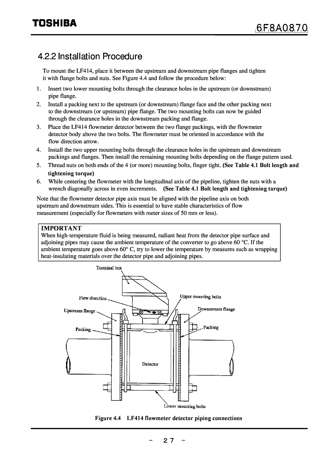
4.2.2 Installation Procedure
Figure 4.4 LF414 flowmeter detector piping connections
- 28 -
Table 4.1 Bolt length and Nut tightening torque
1a Ideal Upstream Straight Pipe Length Installation Requirements
1b Optional “Mount Anywhere” Installation Mount-Anywhere Technology
4.3 Piping Connections
L=5D
2 Pipe Orientation
- 30 -
Figure 4.6 Installation position of the detector
Figure 4.5 Detector Piping Orientation
3 Flow Direction
4 Preventing an Empty Pipe Condition
- 31 -
Figure 4.7 Flow direction arrow on the detector
4.4 Grounding
1 Grounding of the LF414/LF620F type
- 32 -
Figure 4.10 Grounding the LF414/LF620F Type
2 Grounding of the LF414 type
- 33 -
Safety Precautions for Wiring
5.Wiring
- 34 -
6F8A0870
- 35 -
„ Install a switch and fuse to isolate the
independently from power equipment. 100 ohm
Notes on wiring
5.1 Cables
- 36 -
Table 5.1 Installation Cables
5.3 Notes on Wiring 5.3.1 Notes on Instrumentation-Converter Wiring
5.3.2 Notes on Wiring of the Separate type LF414
5.2 External Device Connections and Grounding
- 37 -
5.4 Wiring 5.4.1 Terminal Treatment of Cables
1 Power cable, current output cable, digital I/O cables
Separate 2 Excitation cable
- 38 -
3 Connecting the input signal cable
Notes on signal cable shield processing work
- 39 -
Figure 5.3 Terminal Treatment of Flow Rate Signal Cable
- 40 -
5.4.2 Cable Connection
Figure 5.5 Connecting a Cable to Terminal Block
6. Operation
Preparatory check
- 41 -
„ Check the wiring between the converter and related instruments
7. Maintenance and Troubleshooting
Safety precaution for Maintenance and Troubleshooting
- 42 -
„ Do not conduct wiring work when power is applied
7.1 Maintenance
„ Cleaning
Check/Replacement of the display unit
materials
7.2 Troubleshooting
7.2.1 Flow rate is not indicated
- 44 -
START Are power supplies correct NO for each device? YES
7.2.2 Flow rate indicated is not correct
- 45 -
Perform the zero adjustment Refer to combined converters manual
Clean the inside of the detector pipe
7.2.3 Flow rate indication is not stable
- 46 -
Is power supply voltage
Use a power supply within the specified range
- 47 -
8. Principle of Operation
Square-Wave Excitation Figure 8.1 Principle of Operation
9. Specifications
9.1Specifications
- 48 -
Measurement range in terms of flow velocity
Electrical conductivity μS/cm
- 49 -
Figure 9.1 Electrical Conductivity vs. Cable Length
- 50 -
Table 9.1 Standard Flow Range
- 51 -
Table 9.2 Flow velocity vs. flow volume
Unit gal/min
Unit m3/h
- 52 -
Table 9.3 Type Specification Code
9.2 Type Specification Code
- 53 -
Table 9.4 Type Specification Code Exciting Cable and Signal Cable
Exciting cable length Nominal cross-sectional area Overall diameter
10. Outline Dimensions
10.1 Outline dimensions of LF414/LF600F, LF414/LF610F
1 Meter size of 1/2 inch 15mm
2 Meter size of 1 inch 25mm
3 Meter size of 1 1/2 to 8 inch 40 to 200mm
- 55 -
- 56 -
10.2 Outline dimensions of LF414/LF620F
Waight approx 9 lb 4kg
- 57 -
- 58 -
10.3 Outline dimensions of LF414
Waight approx 7 lb 3kg
- 59 -
Appendix 1-1 A system block diagram for LF414/LF600F, LF414/LF610F
- 60 -
1-2 A system block diagram for LF414/LF620F
- 61 -
2-1 A system block diagram for LF414
- 62 -
- 63 -
Distributor Address Name
Phone number (
Product code
FCF50017
Top
Page
Image
Contents