Manuals
/
Toshiba
/
Lawn and Garden
/
Metal Detector
Toshiba
LF414
manual
Piping Connections, 6F8A0870, L=5D, L=10D
Models:
LF414
1
30
65
65
Download
65 pages
63.14 Kb
27
28
29
30
31
32
33
34
Troubleshooting
Specification
Install
Explanation of signal words
Wiring
Dimension
Maintenance
Zero Adjustment
About Safety Precautions
„ Turn off mains power before
Page 30
Image 30
Page 29
Page 31
Page 30
Image 30
Page 29
Page 31
Contents
6F8A0870
About Safety Precautions
6F8A0870
- 1 -
Integral type LF414/LF600F, LF414/LF610F, LF414/LF620F
Safety symbols
SAFETY PRECAUTIONS
Explanation of signal words
- 2 -
DON’T
SAFETY PRECAUTIONS Safety Precautions for Installation and Wiring
- 3 -
„ Do not modify or disassemble the enclosure
DON’T
SAFETY PRECAUTIONS continued
Safety Precautions for Installation and Wiring
- 4 -
Usage limitation
Safety Precautions for Maintenance and Inspection
Warranty and Limitation of Liability
- 5 -
・Places where excessive vibration or mechanical shock occurs
Handling Precautions
- 6 -
2 Wire cables correctly and securely
Handling Precautions continued
- 7 -
Table of Contents
- 8 -
1.2 Strage
1. Product Inspection and Storage
1.1 Product Inspection
- 9 -
- 10 -
Features
2. Overview
5 Intelligent functions
3.1.1 Appearance of LF414/LF600F, LF414/LF610F
3. Names of Parts
3.1 Appearance
Integral 1 Meter size of 1/2 inch 15mm
Figure 3.1.2 Appearance of LF414/LF600F, LF610F Meter size 1 inch25mm
2 Meter size of 1inch 25mm
- 12 -
Ground terminal for converter
Figure 3.1.3 Appearance of LF414/LF600F, LF610F
3 Meter size of 1 1/2 to 4 inch 40 to 100mm
- 13 -
Meter size 1 1/2 to 4 inch 40 to 100mm
Lifting Lugs
4 Meter size of 6 and 8 inch 150 and 200mm
- 14 -
provided
Figure 3.1.5 Appearance of LF414/LF620F Meter size 1/2inch15mm
3.1.2 Appearance of LF414/LF620F
- 15 -
Ground terminal for converter Flow direction arrow Detector
- 16 -
Figure 3.1.6 Appearance of LF414/LF620F Meter size 1 inch25mm
Ground terminal for converter Flow direction arrow
- 17 -
Figure 3.1.7 Appearance of LF414/LF620F
Meter size 6 and 8 inch 150 and 200mm
- 18 -
Figure 3.1.8 Appearance of LF414/LF620F
Ground terminal for converter Lifting Lugs
- 19 -
3.1.3 Appearance of LF414
Separate 1 Meter size of 1/2 inch 15mm
Signal cable
Figure 3.1.10 Appearance of LF414 Meter size 1 inch25mm
- 20 -
for Signal cable
for Excitation cable
Figure 3.1.11 Appearance of LF414
- 21 -
Signal cable
Excitation cable
- 22 -
Figure 3.1.12 Appearance of LF414
Meter size 6 and 8 inch150 and 200mm
3.2.2 Terminal Block Construction of LF414 Type
Signal cable terminal
3.2 Construction of the terminal blocks
- 23 -
- 24 -
4. Installation
Safety Precautions for Installation
„ Use an appropriate device to carry and install
- 25 -
4.1 Notes on Selecting the Installation Location
4.2 Mounting Procedure 4.2.1 Pipe checks
2. Avoid places where excessive pipe vibration occurs
- 26 -
Figure 4.2 Example of Pipe Fixing Procedure
Figure 4.3 Model Diagram of Unsupported Pipes
4.2.2 Installation Procedure
- 27 -
Figure 4.4 LF414 flowmeter detector piping connections
- 28 -
Table 4.1 Bolt length and Nut tightening torque
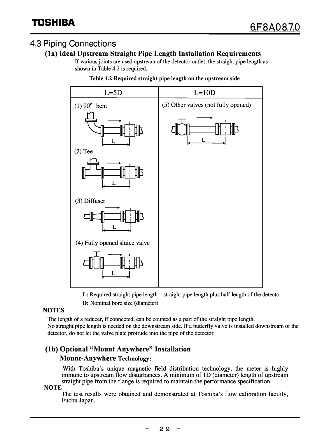
4.3 Piping Connections
1a Ideal Upstream Straight Pipe Length Installation Requirements
1b Optional “Mount Anywhere” Installation Mount-Anywhere Technology
L=5D
Figure 4.6 Installation position of the detector
2 Pipe Orientation
- 30 -
Figure 4.5 Detector Piping Orientation
- 31 -
3 Flow Direction
4 Preventing an Empty Pipe Condition
Figure 4.7 Flow direction arrow on the detector
- 32 -
4.4 Grounding
1 Grounding of the LF414/LF620F type
Figure 4.10 Grounding the LF414/LF620F Type
2 Grounding of the LF414 type
- 33 -
5.Wiring
Safety Precautions for Wiring
- 34 -
„ Install a switch and fuse to isolate the
6F8A0870
- 35 -
independently from power equipment. 100 ohm
- 36 -
Notes on wiring
5.1 Cables
Table 5.1 Installation Cables
5.2 External Device Connections and Grounding
5.3 Notes on Wiring 5.3.1 Notes on Instrumentation-Converter Wiring
5.3.2 Notes on Wiring of the Separate type LF414
- 37 -
Separate 2 Excitation cable
5.4 Wiring 5.4.1 Terminal Treatment of Cables
1 Power cable, current output cable, digital I/O cables
- 38 -
- 39 -
3 Connecting the input signal cable
Notes on signal cable shield processing work
Figure 5.3 Terminal Treatment of Flow Rate Signal Cable
5.4.2 Cable Connection
- 40 -
Figure 5.5 Connecting a Cable to Terminal Block
- 41 -
6. Operation
Preparatory check
„ Check the wiring between the converter and related instruments
- 42 -
7. Maintenance and Troubleshooting
Safety precaution for Maintenance and Troubleshooting
„ Do not conduct wiring work when power is applied
Check/Replacement of the display unit
7.1 Maintenance
„ Cleaning
materials
- 44 -
7.2 Troubleshooting
7.2.1 Flow rate is not indicated
START Are power supplies correct NO for each device? YES
Perform the zero adjustment Refer to combined converters manual
7.2.2 Flow rate indicated is not correct
- 45 -
Clean the inside of the detector pipe
Is power supply voltage
7.2.3 Flow rate indication is not stable
- 46 -
Use a power supply within the specified range
8. Principle of Operation
- 47 -
Square-Wave Excitation Figure 8.1 Principle of Operation
- 48 -
9. Specifications
9.1Specifications
Measurement range in terms of flow velocity
- 49 -
Electrical conductivity μS/cm
Figure 9.1 Electrical Conductivity vs. Cable Length
- 50 -
Table 9.1 Standard Flow Range
Unit gal/min
- 51 -
Table 9.2 Flow velocity vs. flow volume
Unit m3/h
Table 9.3 Type Specification Code
- 52 -
9.2 Type Specification Code
Table 9.4 Type Specification Code Exciting Cable and Signal Cable
- 53 -
Exciting cable length Nominal cross-sectional area Overall diameter
1 Meter size of 1/2 inch 15mm
10. Outline Dimensions
10.1 Outline dimensions of LF414/LF600F, LF414/LF610F
2 Meter size of 1 inch 25mm
3 Meter size of 1 1/2 to 8 inch 40 to 200mm
- 55 -
10.2 Outline dimensions of LF414/LF620F
- 56 -
Waight approx 9 lb 4kg
- 57 -
10.3 Outline dimensions of LF414
- 58 -
Waight approx 7 lb 3kg
- 59 -
Appendix 1-1 A system block diagram for LF414/LF600F, LF414/LF610F
- 60 -
1-2 A system block diagram for LF414/LF620F
- 61 -
2-1 A system block diagram for LF414
- 62 -
Phone number (
- 63 -
Distributor Address Name
Product code
FCF50017
Top
Page
Image
Contents