Manuals
/
Toshiba
/
TV and Video
/
Projection Television
Toshiba
P600DL
service manual
Dimensions
Models:
P600DL
1
10
44
44
Download
44 pages
29.4 Kb
7
8
9
10
11
12
13
14
Specs
Parts list
Debugging Flow Diagram
Acceptable Signal Type
.Wiring
Dimension
96pin connector
Disassembly
Adjustment
Safety Precaution
Page 10
Image 10
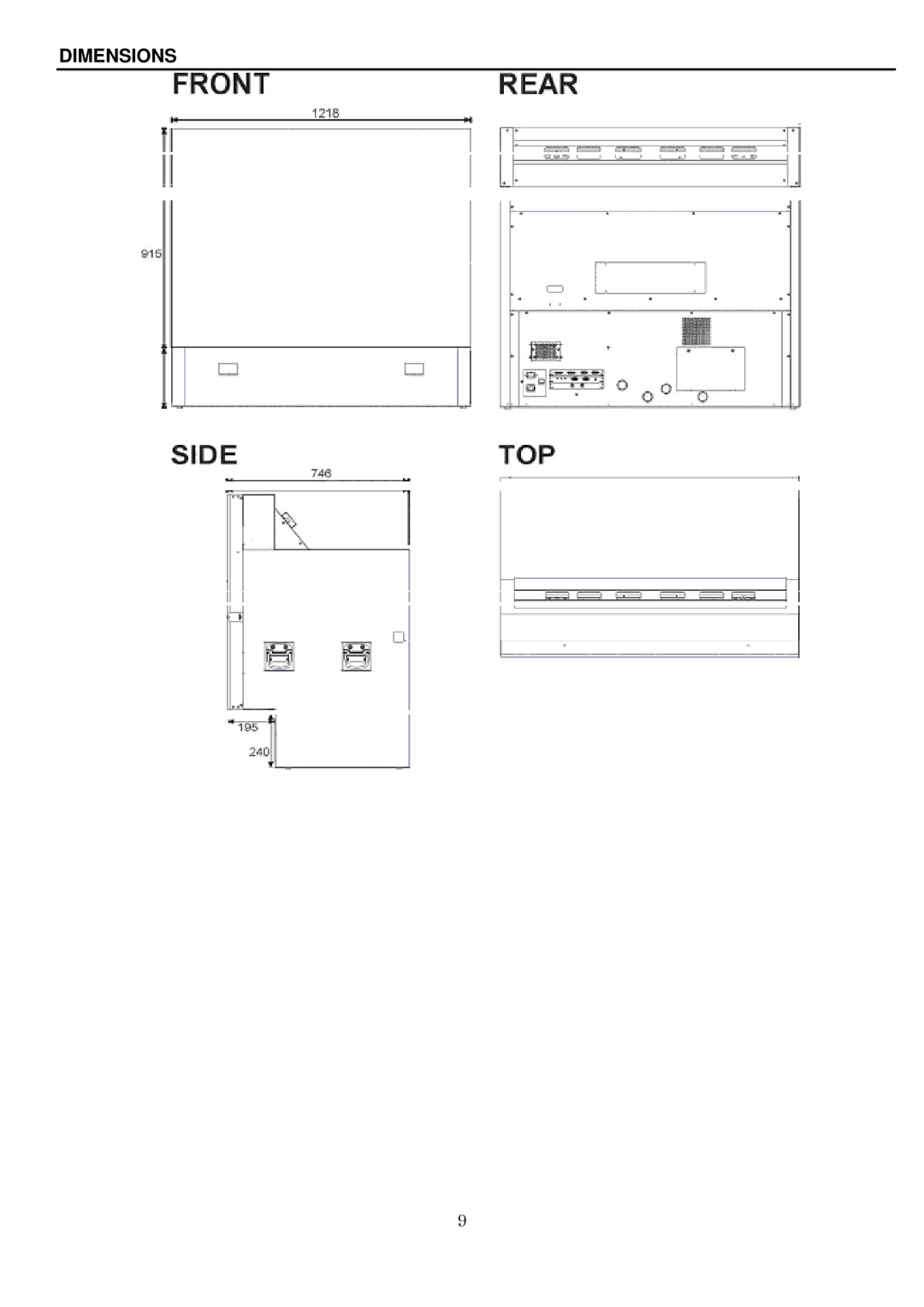
DIMENSIONS
9
Page 9
Page 11
Page 10
Image 10
Page 9
Page 11
Contents
P600DL
Safety Precaution
Contents
Safety Precautions for User
For use of the equipment
For servicing, maintenance and inspection
Safety Precautions for User
Precautions for USE and Maintenance
Request to User
General Descriptions Features
Dimensions
Function of I/O Panel
BNC
Power Switch and Power Indicator
Function of Power Panel
ON/OFF
Specifications
Acceptable Signal Type
Acceptable RGB Input Signal Timing
Horizontal Timing Vertical Timing
Unit-4Unit-3
Connection AT a Multi Projection System
Disassembly
HOW to Replace the Lamp
Diassembly
Power Supply Module Ballast Module Control Module
.LOCATION of KEY Components and Function Module
Exploded View of the Projection Block
96pin connector
.EXPLODED View of the Screen Block and Cabinet
.WIRING
Adjustment
.ENGINE Mount Adjustment
Adjustment
Adjustment
Adjustment
Colour , Tint
Multiple Screen Wall system example
Electronic Circuit Explanation
Electric Circuit Explanation
Stanby
Power FAN Lamp
Power on
FAN Stop
Appendix-2
Cont
VN2
ID.CLR
DMD Driver Board Debug
Page
Debugging Flow Diagram
DMD Driver Board
Bad image- Horizontal bands or lines
Image shifted to left
Parts List
Location No Description 94800807 Ballast Module Assy 100W
Top
Page
Image
Contents