DMD DRIVER BOARD
Debugging Flow Diagram
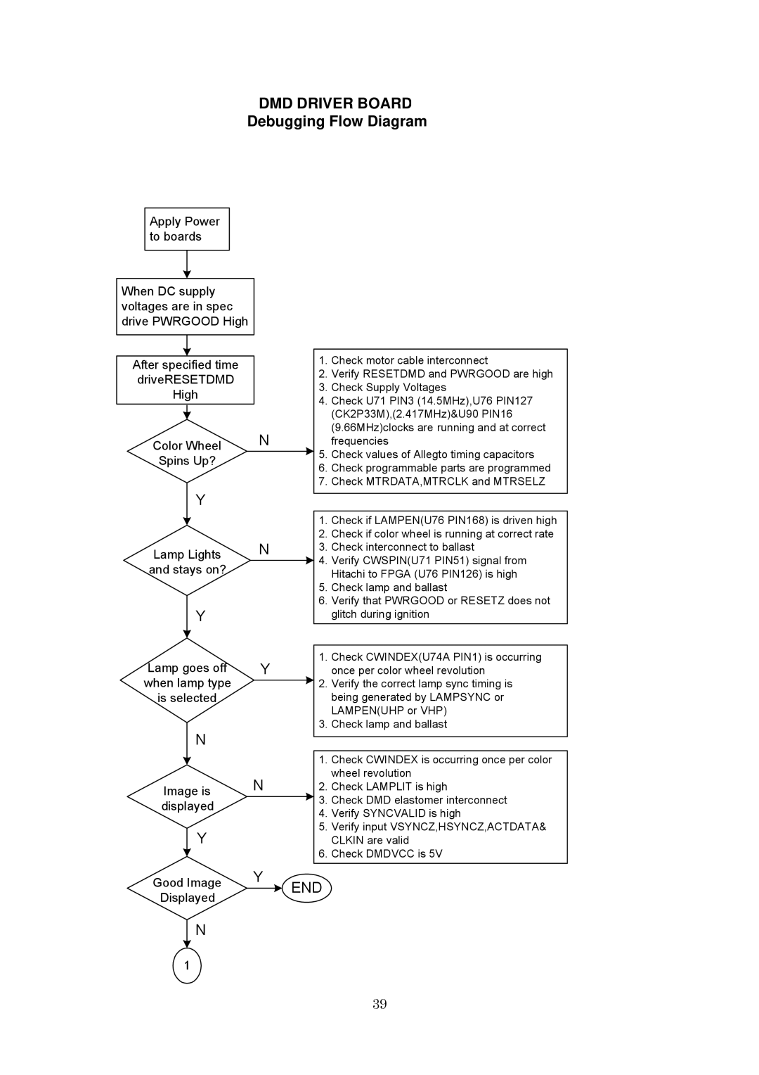
Apply Power to boards
When DC supply voltages are in spec drive PWRGOOD High
After specified time driveRESETDMD High
Color Wheel | N | |
Spins Up? |
| |
| Y |
|
|
| |
|
| N |
Lamp Lights | ||
and stays on? |
| |
Y
Lamp goes off | Y | |
when lamp type |
| |
is selected |
| |
| N |
|
|
| |
|
| N |
Image is | ||
displayed |
| |
Y
1.Check motor cable interconnect
2.Verify RESETDMD and PWRGOOD are high
3.Check Supply Voltages
4.Check U71 PIN3 (14.5MHz),U76 PIN127 (CK2P33M),(2.417MHz)&U90 PIN16 (9.66MHz)clocks are running and at correct
frequencies
![]() 5. Check values of Allegto timing capacitors
5. Check values of Allegto timing capacitors
6.Check programmable parts are programmed
7.Check MTRDATA,MTRCLK and MTRSELZ
1.Check if LAMPEN(U76 PIN168) is driven high
2.Check if color wheel is running at correct rate
3.Check interconnect to ballast
![]() 4. Verify CWSPIN(U71 PIN51) signal from Hitachi to FPGA (U76 PIN126) is high
4. Verify CWSPIN(U71 PIN51) signal from Hitachi to FPGA (U76 PIN126) is high
5.Check lamp and ballast
6.Verify that PWRGOOD or RESETZ does not glitch during ignition
1. Check CWINDEX(U74A PIN1) is occurring once per color wheel revolution
![]() 2. Verify the correct lamp sync timing is being generated by LAMPSYNC or LAMPEN(UHP or VHP)
2. Verify the correct lamp sync timing is being generated by LAMPSYNC or LAMPEN(UHP or VHP)
3. Check lamp and ballast
1.Check CWINDEX is occurring once per color wheel revolution
2.Check LAMPLIT is high
![]() 3. Check DMD elastomer interconnect
3. Check DMD elastomer interconnect
4.Verify SYNCVALID is high
5.Verify input VSYNCZ,HSYNCZ,ACTDATA& CLKIN are valid
6.Check DMDVCC is 5V
Good Image | Y | END |
| ||
Displayed |
|
|
N
1
39