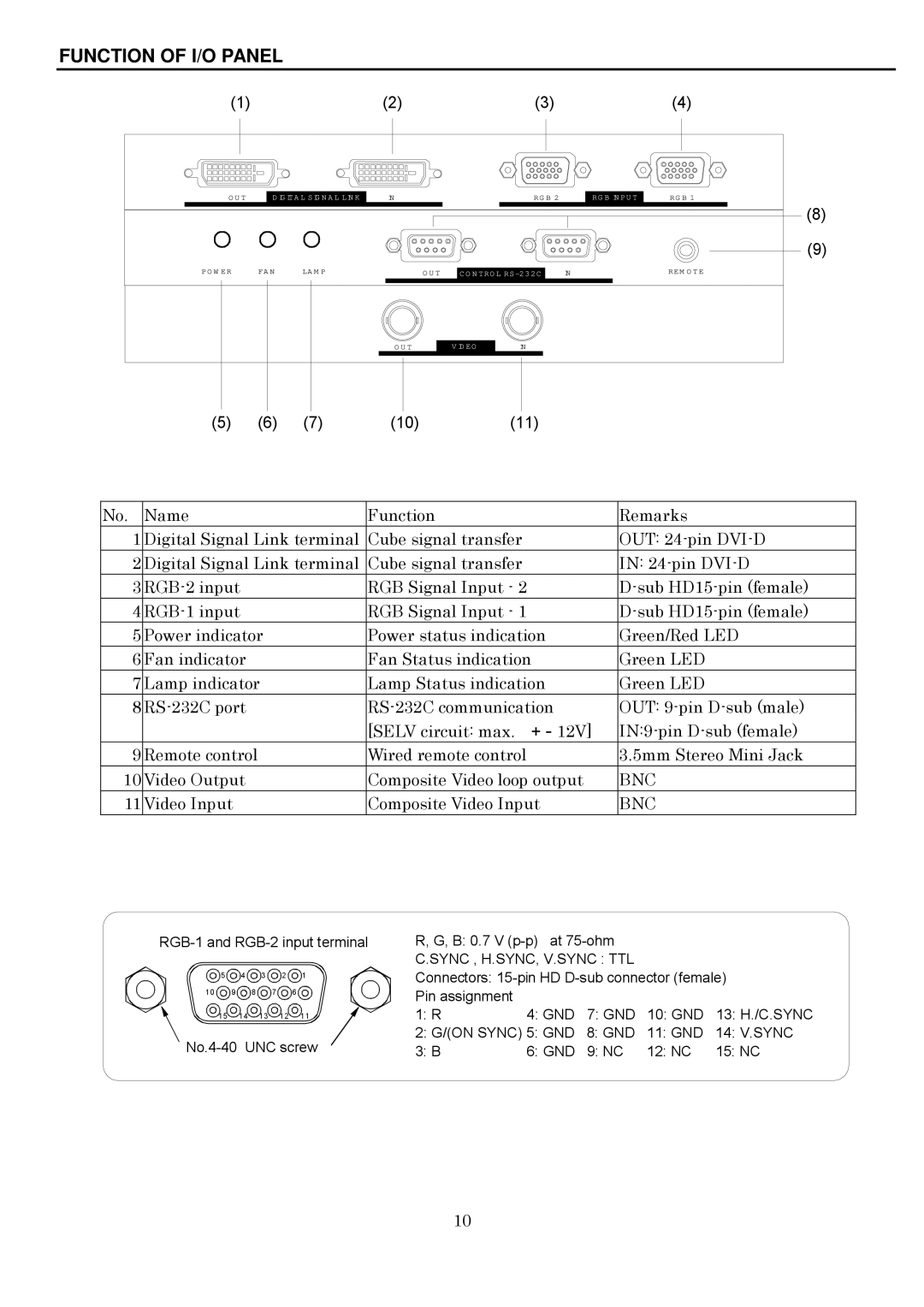
FUNCTION OF I/O PANEL
(1) | (2) | (3) | (4) |
OUT
DIGITAL SIGNAL LINK
IN | RGB 2 | RGB INPUT | RGB 1 |
(8)
(9)
POWER | FAN | LAMP | OUT |
| IN | REMOTE |
CONTROL | ||||||
|
|
|
|
|
|
|
OUT
VIDEO
IN
(5) | (6) | (7) | (10) | (11) |
No. | Name | Function | Remarks |
1 | Digital Signal Link terminal | Cube signal transfer | OUT: |
2 | Digital Signal Link terminal | Cube signal transfer | IN: |
3 | RGB Signal Input - 2 | ||
4 | RGB Signal Input - 1 | ||
5 | Power indicator | Power status indication | Green/Red LED |
6 | Fan indicator | Fan Status indication | Green LED |
7 | Lamp indicator | Lamp Status indication | Green LED |
8 | OUT: | ||
|
| [SELV circuit: max. + - 12V] | |
9 | Remote control | Wired remote control | 3.5mm Stereo Mini Jack |
10 | Video Output | Composite Video loop output | BNC |
11 | Video Input | Composite Video Input | BNC |
![]() 5
5 ![]() 4
4 ![]() 3
3 ![]() 2
2 ![]() 1
1
10 ![]() 9
9 ![]() 8
8 ![]() 7
7 ![]() 6
6 ![]()
15 14 13 12 11
R, G, B: 0.7 V
C.SYNC , H.SYNC, V.SYNC : TTL
Connectors:
Pin assignment |
|
|
|
|
1: R | 4: GND | 7: GND | 10: GND | 13: H./C.SYNC |
2: G/(ON SYNC) 5: GND | 8: GND | 11: GND | 14: V.SYNC | |
3: B | 6: GND | 9: NC | 12: NC | 15: NC |
10
