Phones Module (PHM-7)
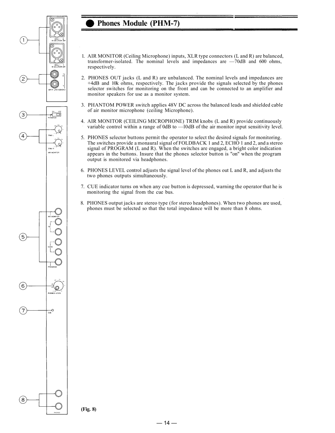
1.AIR MONITOR (Ceiling Microphone) inputs, XLR type connectors (L and R) are balanced,
2.PHONES OUT jacks (L and R) are unbalanced. The nominal levels and impedances are +4dB and 10k ohms, respectively. The jacks provide the signals selected by the phones selector switches for monitoring on the front and can be connected to an amplifier and monitor speakers for use as a monitor system.
3.PHANTOM POWER switch applies 48V DC across the balanced leads and shielded cable of air monitor microphone (ceiling Microphone).
4.AIR MONITOR (CEILING MICROPHONE) TRIM knobs (L and R) provide continuously variable control within a range of 0dB to
5.PHONES selector buttons permit the operator to select the desired signals for monitoring. The switches provide a monaural signal of FOLDBACK 1 and 2, ECHO 1 and 2, and a stereo signal of PROGRAM (L and R). When the switches are engaged, a bright color indication appears in the buttons. Insure that the phones selector button is "on" when the program output is monitored via headphones.
6.PHONES LEVEL control adjusts the signal level of the phones out L and R, and adjusts the two phones outputs simultaneously.
7.CUE indicator turns on when any cue button is depressed, warning the operator that he is monitoring the signal from the cue bus.
8.PHONES output jacks are stereo type (for stereo headphones). When two phones are used, phones must be selected so that the total impedance will be more than 8 ohms.
(Fig. 8)
— 14 —
