Input Module (IPM-7)
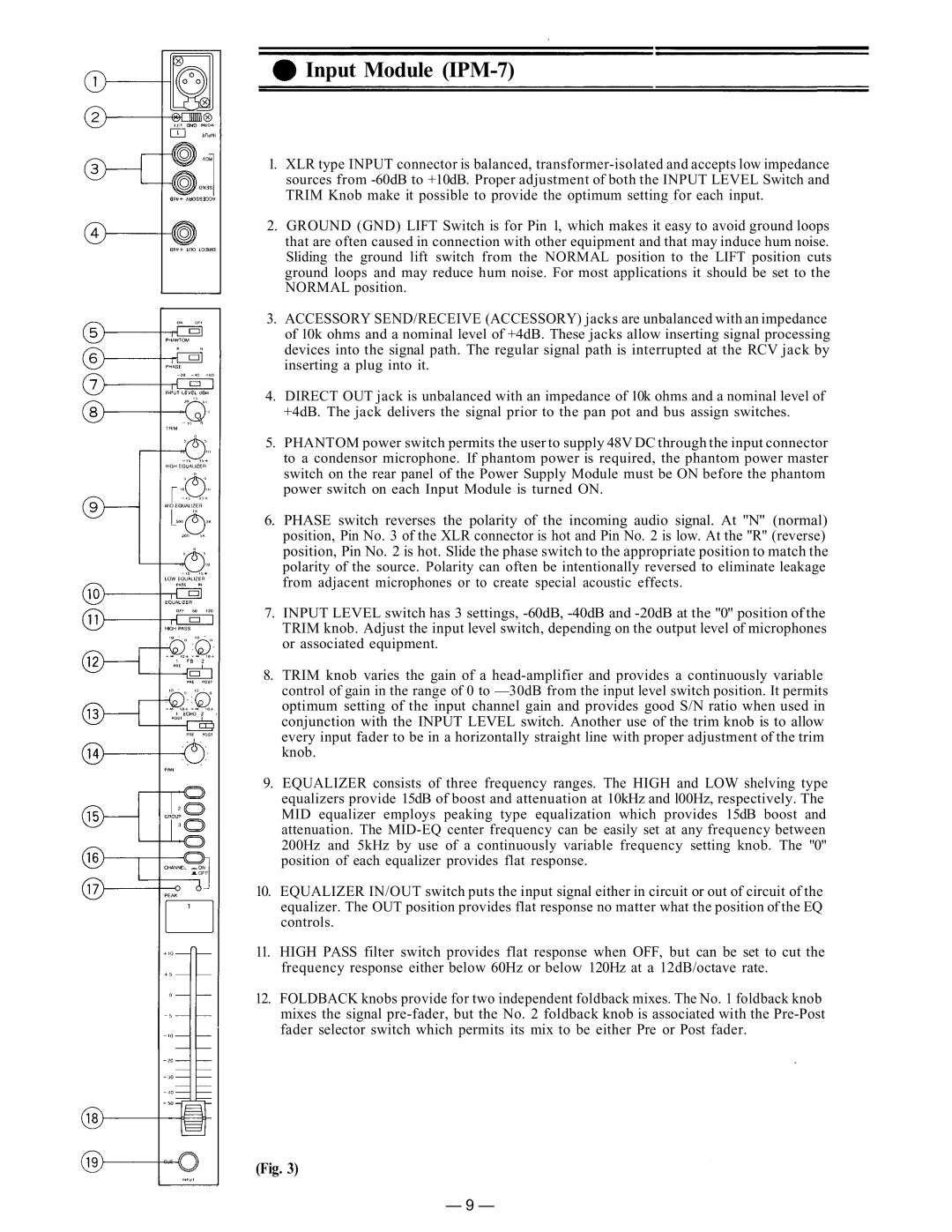
1.XLR type INPUT connector is balanced,
2.GROUND (GND) LIFT Switch is for Pin 1, which makes it easy to avoid ground loops that are often caused in connection with other equipment and that may induce hum noise. Sliding the ground lift switch from the NORMAL position to the LIFT position cuts ground loops and may reduce hum noise. For most applications it should be set to the NORMAL position.
3.ACCESSORY SEND/RECEIVE (ACCESSORY) jacks are unbalanced with an impedance of 10k ohms and a nominal level of +4dB. These jacks allow inserting signal processing devices into the signal path. The regular signal path is interrupted at the RCV jack by inserting a plug into it.
4.DIRECT OUT jack is unbalanced with an impedance of 10k ohms and a nominal level of +4dB. The jack delivers the signal prior to the pan pot and bus assign switches.
5.PHANTOM power switch permits the user to supply 48V DC through the input connector to a condensor microphone. If phantom power is required, the phantom power master switch on the rear panel of the Power Supply Module must be ON before the phantom power switch on each Input Module is turned ON.
6.PHASE switch reverses the polarity of the incoming audio signal. At "N" (normal) position, Pin No. 3 of the XLR connector is hot and Pin No. 2 is low. At the "R" (reverse) position, Pin No. 2 is hot. Slide the phase switch to the appropriate position to match the polarity of the source. Polarity can often be intentionally reversed to eliminate leakage from adjacent microphones or to create special acoustic effects.
7.INPUT LEVEL switch has 3 settings,
8.TRIM knob varies the gain of a
9.EQUALIZER consists of three frequency ranges. The HIGH and LOW shelving type equalizers provide 15dB of boost and attenuation at 10kHz and l00Hz, respectively. The MID equalizer employs peaking type equalization which provides 15dB boost and attenuation. The
10.EQUALIZER IN/OUT switch puts the input signal either in circuit or out of circuit of the equalizer. The OUT position provides flat response no matter what the position of the EQ controls.
11.HIGH PASS filter switch provides flat response when OFF, but can be set to cut the frequency response either below 60Hz or below 120Hz at a 12dB/octave rate.
12.FOLDBACK knobs provide for two independent foldback mixes. The No. 1 foldback knob mixes the signal
(Fig. 3)
— 9 —