Program Module (PGM-7)
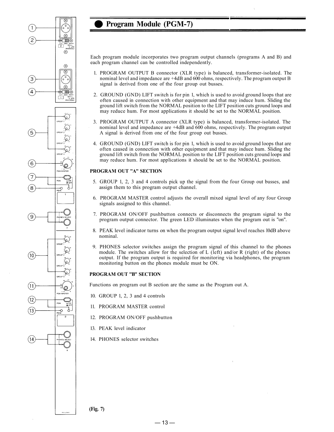
Each program module incorporates two program output channels (programs A and B) and each program channel can be controlled independently.
1.PROGRAM OUTPUT B connector (XLR type) is balanced,
2.GROUND (GND) LIFT switch is for pin 1, which is used to avoid ground loops that are often caused in connection with other equipment and that may induce hum. Sliding the ground lift switch from the NORMAL position to the LIFT position cuts ground loops and may reduce hum. For most applications it should be set to the NORMAL position.
3.PROGRAM OUTPUT A connector (XLR type) is balanced,
4.GROUND (GND) LIFT switch is for pin 1, which is used to avoid ground loops that are often caused in connection with other equipment and that may induce hum. Sliding the ground lift switch from the NORMAL position to the LIFT position cuts ground loops and may reduce hum. For most applications it should be set to the NORMAL position.
PROGRAM OUT "A" SECTION
5.GROUP 1, 2, 3 and 4 controls pick up the signal from the four Group out busses, and assign them to this program output channel.
6.PROGRAM MASTER control adjusts the overall mixed signal level of any four Group signals assigned to this channel.
7.PROGRAM ON/OFF pushbutton connects or disconnects the program signal to the program output connector. The green LED illuminates when the program out is "on".
8.PEAK level indicator turns on when the program output signal level reaches l0dB above nominal.
9.PHONES selector switches assign the program signal of this channel to the phones module. The switches allow for the selection of L (left) and/or R (right) of the phones output. If the program output is required for monitoring via headphones, the program monitoring button on the phones module must be ON.
PROGRAM OUT "B" SECTION
Functions on program out B section are the same as the Program out A.
10.GROUP 1, 2, 3 and 4 controls
11.PROGRAM MASTER control
12.PROGRAM ON/OFF pushbutton
13.PEAK level indicator
14.PHONES selector switches
(Fig. 7)
— 13 —