Meter Panel (RXM-7-25, RXM-7-35, RXM-7-43)
METER PANEL
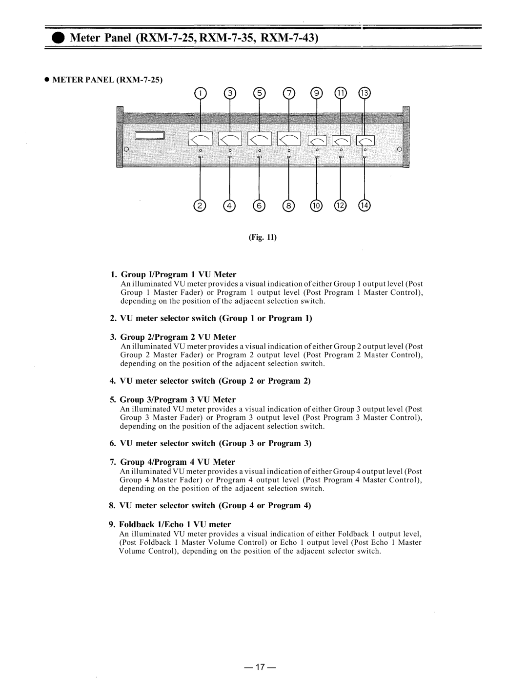
(Fig. 11)
1.Group I/Program 1 VU Meter
An illuminated VU meter provides a visual indication of either Group 1 output level (Post Group 1 Master Fader) or Program 1 output level (Post Program 1 Master Control), depending on the position of the adjacent selection switch.
2.VU meter selector switch (Group 1 or Program 1)
3.Group 2/Program 2 VU Meter
An illuminated VU meter provides a visual indication of either Group 2 output level (Post Group 2 Master Fader) or Program 2 output level (Post Program 2 Master Control), depending on the position of the adjacent selection switch.
4.VU meter selector switch (Group 2 or Program 2)
5.Group 3/Program 3 VU Meter
An illuminated VU meter provides a visual indication of either Group 3 output level (Post
Group 3 Master Fader) or Program 3 output level (Post Program 3 Master Control), depending on the position of the adjacent selection switch.
6.VU meter selector switch (Group 3 or Program 3)
7.Group 4/Program 4 VU Meter
An illuminated VU meter provides a visual indication of either Group 4 output level (Post Group 4 Master Fader) or Program 4 output level (Post Program 4 Master Control),
depending on the position of the adjacent selection switch.
8.VU meter selector switch (Group 4 or Program 4)
9.Foldback 1/Echo 1 VU meter
An illuminated VU meter provides a visual indication of either Foldback 1 output level, (Post Foldback 1 Master Volume Control) or Echo 1 output level (Post Echo 1 Master
Volume Control), depending on the position of the adjacent selector switch.
— 17 —
