*Equalizer IN/OUT Switch
Precise equalizer adjustment can be made while comparing the equalized sound effect with the flat sound by use of the Equalizer IN/OUT switch.
*Foldback 1, 2 and Echo 1, 2
The block diagram indicates the overall signal flow of the FB and Echo circuits. The FB circuit is basically designed to derive the pre fader signal mainly, and the Echo circuit the post fader signal. The
*Group/Foldback, Group/Echo Modules
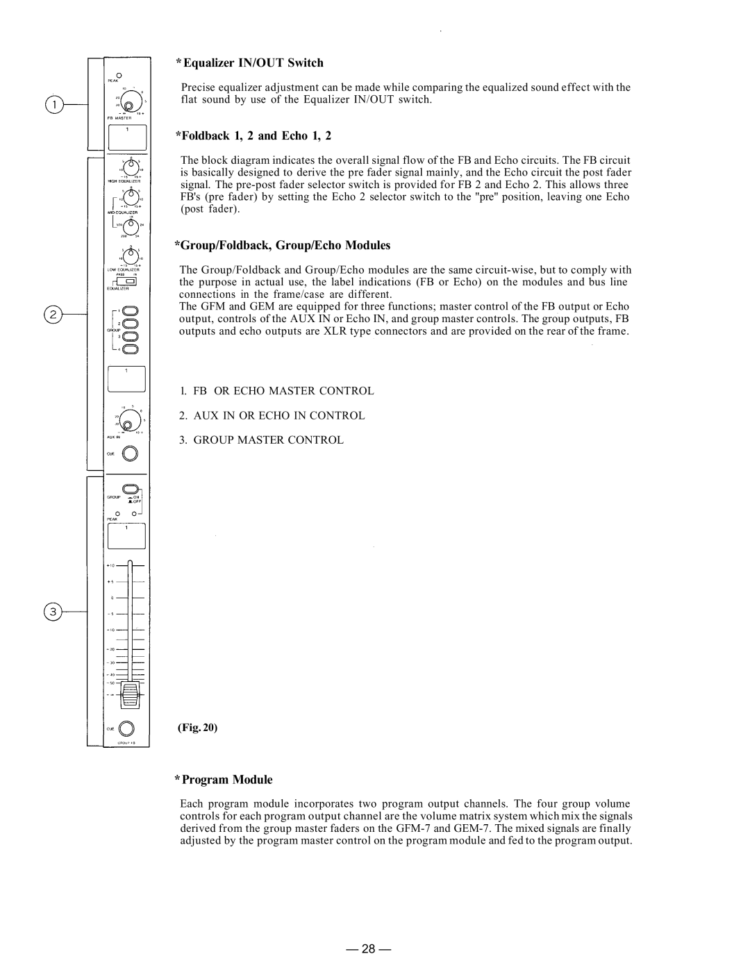
The Group/Foldback and Group/Echo modules are the same
The GFM and GEM are equipped for three functions; master control of the FB output or Echo output, controls of the AUX IN or Echo IN, and group master controls. The group outputs, FB outputs and echo outputs are XLR type connectors and are provided on the rear of the frame.
1.FB OR ECHO MASTER CONTROL
2.AUX IN OR ECHO IN CONTROL
3.GROUP MASTER CONTROL
(Fig. 20)
*Program Module
Each program module incorporates two program output channels. The four group volume controls for each program output channel are the volume matrix system which mix the signals derived from the group master faders on the
— 28 —
