Group/Foldback Module (GFM-7)
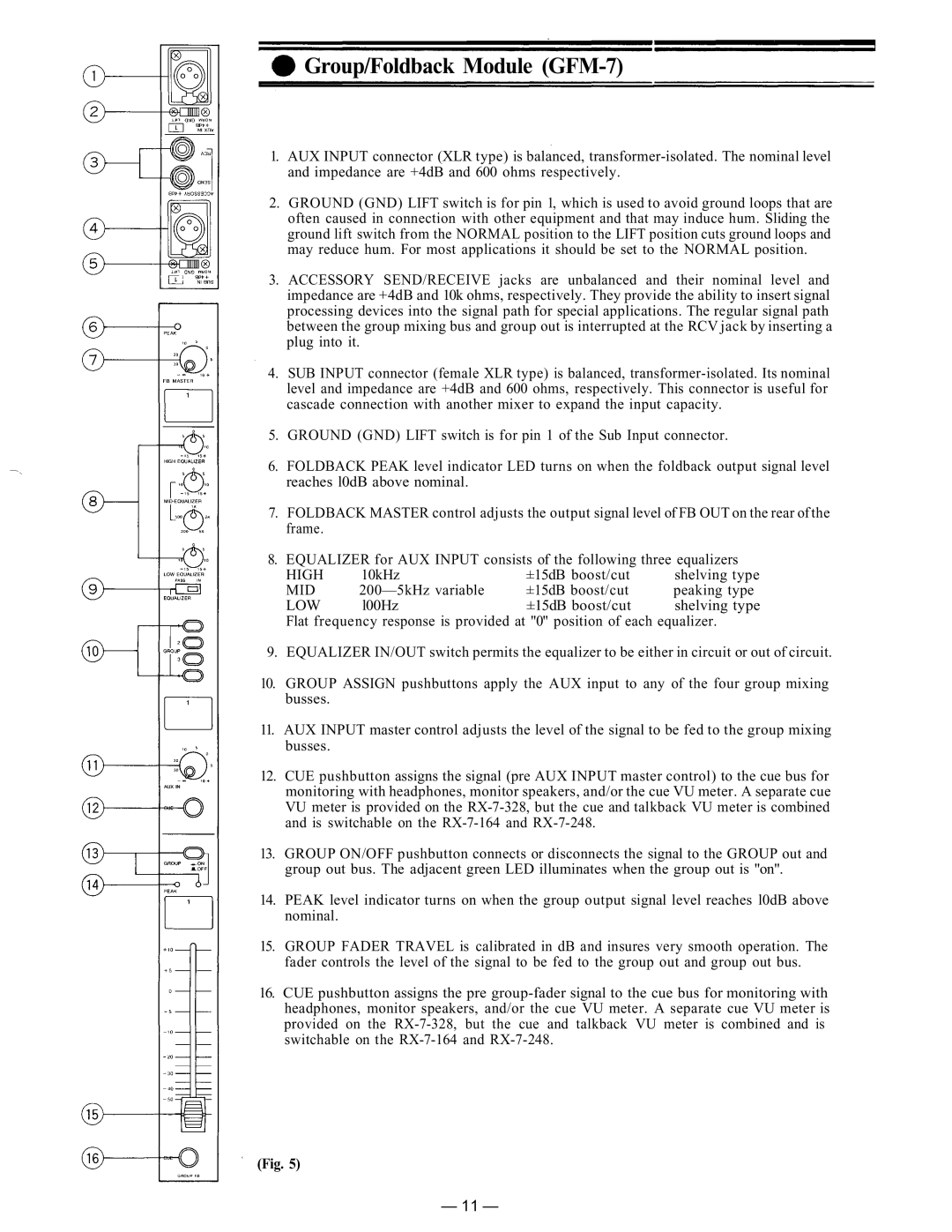
1.AUX INPUT connector (XLR type) is balanced,
2.GROUND (GND) LIFT switch is for pin 1, which is used to avoid ground loops that are often caused in connection with other equipment and that may induce hum. Sliding the ground lift switch from the NORMAL position to the LIFT position cuts ground loops and may reduce hum. For most applications it should be set to the NORMAL position.
3.ACCESSORY SEND/RECEIVE jacks are unbalanced and their nominal level and impedance are +4dB and 10k ohms, respectively. They provide the ability to insert signal processing devices into the signal path for special applications. The regular signal path between the group mixing bus and group out is interrupted at the RCV jack by inserting a plug into it.
4.SUB INPUT connector (female XLR type) is balanced,
5.GROUND (GND) LIFT switch is for pin 1 of the Sub Input connector.
6.FOLDBACK PEAK level indicator LED turns on when the foldback output signal level reaches l0dB above nominal.
7.FOLDBACK MASTER control adjusts the output signal level of FB OUT on the rear of the frame.
8. EQUALIZER for AUX INPUT consists of the following three equalizers
HIGH | 10kHz | ±15dB boost/cut | shelving type |
MID | ±15dB boost/cut | peaking type | |
LOW | l00Hz | ±15dB boost/cut | shelving type |
Flat frequency response is provided at "0" position of each equalizer.
9.EQUALIZER IN/OUT switch permits the equalizer to be either in circuit or out of circuit.
10.GROUP ASSIGN pushbuttons apply the AUX input to any of the four group mixing busses.
11.AUX INPUT master control adjusts the level of the signal to be fed to the group mixing busses.
12.CUE pushbutton assigns the signal (pre AUX INPUT master control) to the cue bus for monitoring with headphones, monitor speakers, and/or the cue VU meter. A separate cue VU meter is provided on the
13.GROUP ON/OFF pushbutton connects or disconnects the signal to the GROUP out and group out bus. The adjacent green LED illuminates when the group out is "on".
14.PEAK level indicator turns on when the group output signal level reaches l0dB above nominal.
15.GROUP FADER TRAVEL is calibrated in dB and insures very smooth operation. The fader controls the level of the signal to be fed to the group out and group out bus.
16.CUE pushbutton assigns the pre
(Fig. 5)
— 11 —