Talkback Module (TBM-7)
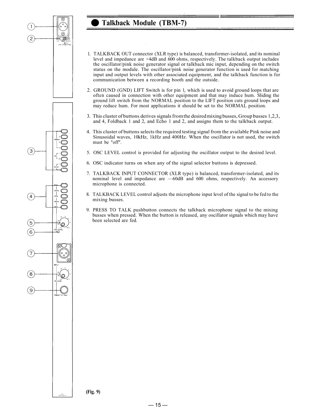
1.TALKBACK OUT connector (XLR type) is balanced,
2.GROUND (GND) LIFT Switch is for pin 1, which is used to avoid ground loops that are often caused in connection with other equipment and that may induce hum. Sliding the ground lift switch from the NORMAL position to the LIFT position cuts ground loops and may reduce hum. For most applications it should be set to the NORMAL position.
3.This cluster of buttons derives signals from the desired mixing busses, Group busses 1,2,3, and 4, Foldback 1 and 2, and Echo 1 and 2, and assigns them to the talkback output.
4.This cluster of buttons selects the required testing signal from the available Pink noise and Sinusoidal waves, 10kHz, 1kHz and 400Hz. When the oscillator is not used, the switch must be "off".
5.OSC LEVEL control is provided for adjusting the oscillator output to the desired level.
6.OSC indicator turns on when any of the signal selector buttons is depressed.
7.TALKBACK INPUT CONNECTOR (XLR type) is balanced,
8.TALKBACK LEVEL control adjusts the microphone input level of the signal to be fed to the mixing busses.
9.PRESS TO TALK pushbutton connects the talkback microphone signal to the mixing busses when pressed. When the button is released, any oscillator signals which may have been selected are fed.
(Fig. 9)
— 15 —