CG-PRC007-EN specifications
The Trane CG-PRC007-EN is a robust product within the Trane line of commercial rooftop units, designed to meet the heating and cooling needs of various commercial applications. This unit showcases advanced technologies and features aimed to enhance efficiency, reliability, and user comfort.One of the standout characteristics of the CG-PRC007-EN is its commitment to energy efficiency. The unit incorporates high-efficiency compressors and a variable-speed fan motor, ensuring that the system can adjust its operation based on the demand, thus optimizing energy consumption. This is particularly advantageous in commercial settings, where climate control requirements can fluctuate throughout the day.
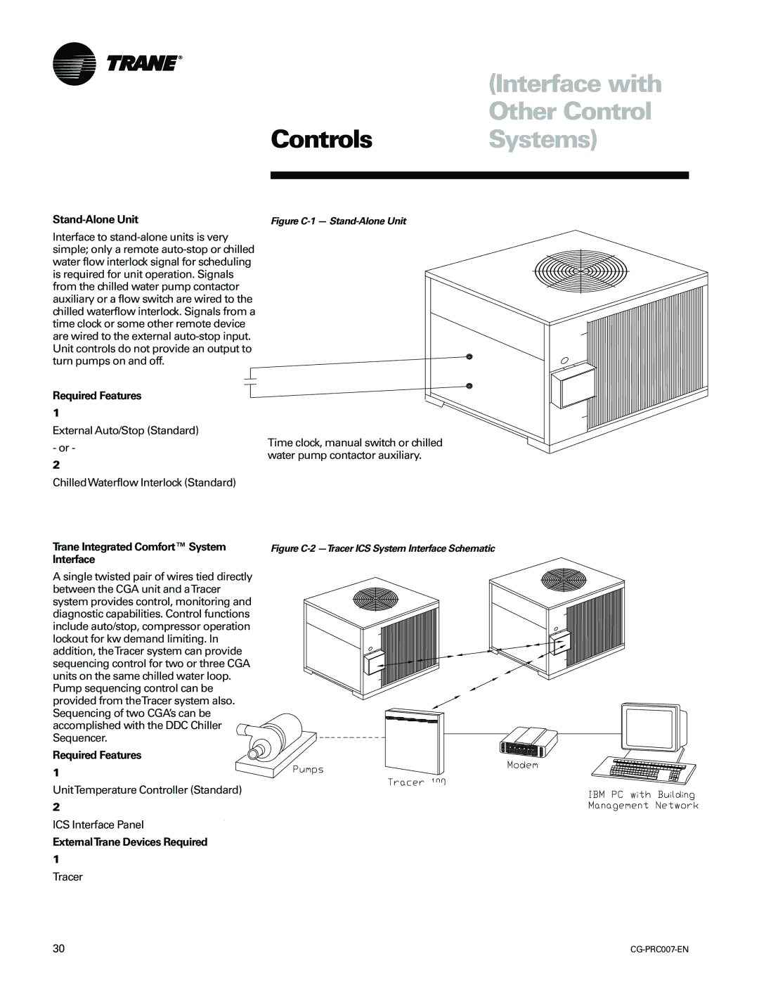
Additionally, the unit is engineered with a smart control system that allows for easy integration with building management systems. This feature enables real-time monitoring and adjustments, helping facility managers maintain optimal comfort levels while also minimizing operational costs. Users are able to access performance data and system diagnostics remotely, promoting proactive maintenance and reducing downtime.
Durability and longevity are critical factors for commercial HVAC systems, and the CG-PRC007-EN is designed with this in mind. The unit features a corrosion-resistant cabinet and components that withstand harsh weather conditions, ensuring reliability in outdoor installations. Its robust construction helps mitigate noise levels, resulting in a quieter operation that is ideal for noise-sensitive environments.
Another key technology within this unit is its advanced airflow management system. This system is designed to provide consistent airflow, enhancing indoor air quality and ensuring that every corner of the space benefits from appropriate heating or cooling. The CG-PRC007-EN also offers a variety of customization options for air filters, ensuring that the specific needs of each application are met.
Furthermore, the unit is compliant with the latest environmental regulations, including those set forth by the EPA. It utilizes eco-friendly refrigerants that minimize environmental impact without sacrificing performance. This makes the CG-PRC007-EN an excellent choice for companies committed to sustainability and energy efficiency.
In summary, the Trane CG-PRC007-EN combines innovative technology, energy efficiency, and reliability, making it an ideal solution for commercial heating and cooling needs. Its advanced features, durability, and eco-friendly design position it as a leader in the commercial rooftop unit market.

