period two
Sound Perception and
Rating Methods
notes
Room Criteria (RC) Curves
| 80 | A |
|
|
|
|
|
|
|
mPa | 70 | B |
|
|
|
|
|
|
|
60 |
|
|
|
|
|
|
|
| |
dB ref 20 |
|
|
|
|
|
|
|
| |
50 |
|
|
| D |
|
|
|
| |
pressure, | 40 |
|
|
|
|
|
|
| |
|
|
|
|
|
|
| E | ||
|
|
|
|
| C | ||||
sound | 30 |
|
|
|
| ||||
20 |
|
|
|
|
|
|
| ||
|
|
|
|
|
|
|
| ||
|
|
|
|
|
|
|
|
| |
| 10 |
|
|
|
|
|
|
| |
| 31.5 | 63 | 125 | 250 | 500 | 1,000 | 2,000 | 4,000 | |
|
| ||||||||
Figure 29 |
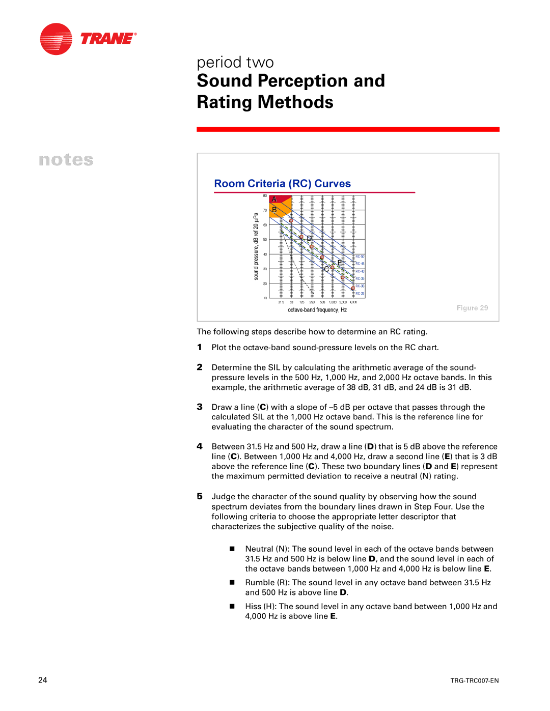
The following steps describe how to determine an RC rating.
1Plot the
2Determine the SIL by calculating the arithmetic average of the sound- pressure levels in the 500 Hz, 1,000 Hz, and 2,000 Hz octave bands. In this example, the arithmetic average of 38 dB, 31 dB, and 24 dB is 31 dB.
3Draw a line (C) with a slope of
4Between 31.5 Hz and 500 Hz, draw a line (D) that is 5 dB above the reference line (C). Between 1,000 Hz and 4,000 Hz, draw a second line (E) that is 3 dB above the reference line (C). These two boundary lines (D and E) represent the maximum permitted deviation to receive a neutral (N) rating.
5Judge the character of the sound quality by observing how the sound spectrum deviates from the boundary lines drawn in Step Four. Use the following criteria to choose the appropriate letter descriptor that characterizes the subjective quality of the noise.
nNeutral (N): The sound level in each of the octave bands between 31.5 Hz and 500 Hz is below line D, and the sound level in each of the octave bands between 1,000 Hz and 4,000 Hz is below line E.
nRumble (R): The sound level in any octave band between 31.5 Hz and 500 Hz is above line D.
nHiss (H): The sound level in any octave band between 1,000 Hz and 4,000 Hz is above line E.
24 |
|
