Speaker Basics, Continued
Power Rating | Speakers used for emergency voice/alarm communication system are wired as “Constant Voltage” |
| systems, where the maximum power output of the amplifier is obtained at a certain speaker |
| voltage, such as 25 V or 70.7 V. The power output of a speaker, and thus the resulting SPL is |
| controlled by wattage taps on the speakers themselves. The minimum wattage tap for a |
| UL Standard 1480 listed speaker is 1/4 W. For example, the Simplex 4902 Series speakers have |
| wattage taps in 3 dB increments: 1/4 W, 1/2 W, 1 W and 2 W. Each wattage tap doubles the |
| power delivered by the speaker, and so increases the SPL output by 3 dB for each increasing tap. |
| An increase of 3 dB is considered a just noticeable increase in SPL, changing the wattage tap from |
| 1/4 W to 2 W increases the perceived loudness by slightly less than double. |
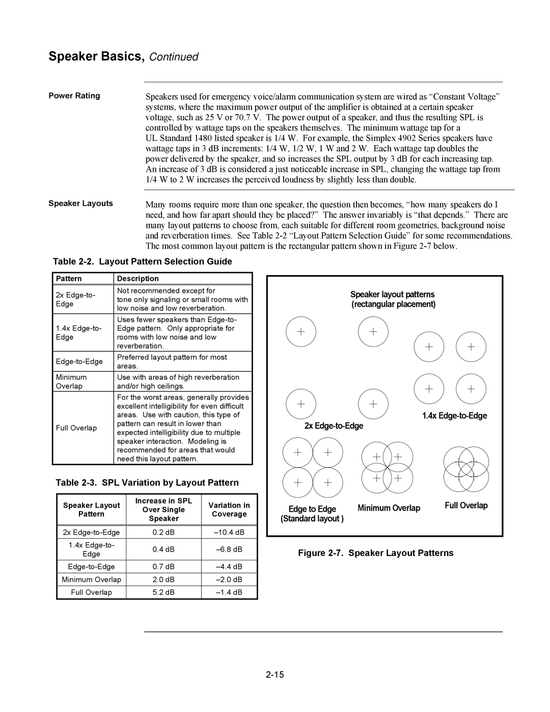
Speaker Layouts | Many rooms require more than one speaker, the question then becomes, “how many speakers do I |
| need, and how far apart should they be placed?” The answer invariably is “that depends.” There are |
| many layout patterns to choose from, each suitable for different room geometries, background noise |
| and reverberation times. See Table |
| The most common layout pattern is the rectangular pattern shown in Figure |
Table 2-2. Layout Pattern Selection Guide
Pattern | Description | |
2x | Not recommended except for | |
tone only signaling or small rooms with | ||
Edge | ||
low noise and low reverberation. | ||
| ||
| Uses fewer speakers than | |
1.4x | Edge pattern. Only appropriate for | |
Edge | rooms with low noise and low | |
| reverberation. | |
Preferred layout pattern for most | ||
areas. | ||
| ||
Minimum | Use with areas of high reverberation | |
Overlap | and/or high ceilings. | |
| For the worst areas, generally provides | |
| excellent intelligibility for even difficult | |
| areas. Use with caution, this type of | |
Full Overlap | pattern can result in lower than | |
expected intelligibility due to multiple | ||
| ||
| speaker interaction. Modeling is | |
| recommended for areas that would | |
| need this layout pattern. |
Table 2-3. SPL Variation by Layout Pattern
Speaker Layout | Increase in SPL | Variation in | |
Over Single | |||
Pattern | Coverage | ||
Speaker | |||
|
| ||
2x | 0.2 dB | ||
1.4x | 0.4 dB | ||
Edge | |||
|
| ||
0.7 dB | |||
Minimum Overlap | 2.0 dB | ||
Full Overlap | 5.2 dB |
| Speaker layout patterns |
|
| (rectangular placement) |
|
| 1.4x | |
2x |
| |
Edge to Edge | Minimum Overlap | Full Overlap |
(Standard layout ) |
|
|
