FPA NZ Listing number VF/117 AS/NZS 3548 1995 Class a
Document Number LT0273 Issue 1.5 24 March
SSL Listing Number Afp1446
NEW Zealand
Amendment LOG
NON-DISCLOSURE Agreement
END User Liability Disclaimer
Trademarks
Table of Contents
11.1
Analogue Loop Design Considerations
MX4428 MXP Engineering /Technical Manual Document LT0273
Device Processing
Chapter Introduction
Product Related
About this Manual
Associated Documentation
Specifications
Standard Related
Terminology
Chapter Responder Loop Design Considerations
MXP Application Considerations
Logical Responders
Logical Responders
Point Allocation For Various Numbers of Logical Responders
NLR
Point to Circuit to Zone Mapping
= Base Address of Responder = Device Number
Implications to System Design
Device Information and Programming
Device Types
MX Devices
814PH Analogue Photoelectric Smoke Detector + Heat Detector
814I Analogue Ionisation Smoke Detector
814H Analogue Heat Detector
814P Analogue Photoelectric Smoke Detector
Mini Input Module MIM801
814CH Analogue CO Carbon monoxide Detector + Heat Detector
Mini Input Module MIM800
Contact Input Module CIM800
Short Circuit Isolator 5BI
Loop Powered Sounder LPS800
Sounder Notification Module SNM800
Sounder Base 814SB and MkII Sounder Base
Compatible Device Summary
Device Function
Device Quantities and Loading
Device Handling Capability
Overview
Maximum Cable Lengths
AC Loading
Cable type Cable length
Calculate DC Load
Isolator Base Loading
Example
Ii Calculate AC Load
Output Control
Circuit alarm
Point alarm
Relay output
Output State Under Exceptional Circumstances
Mode Functional Base Control Remote LED Control
Programming
Prealarm
Detector Parameter Settings Summary
Detector Default Alternate Range Comments
Conversion
Mounting
Device Installation
Precautions
Address & LED Blink Programming
MX4428 Programming
General
2 814H Specifications
814H Heat Detector
3 MX4428 Programming Options 814H
Parameter Description Default
MX4428 Reference Description Default
3 MX4428 Programming Options
2 814I Specifications
814I Ionisation Smoke Detector
8XXI Upper
Tracking Limit
2 814PH & 814P Specifications
3 MX4428 Programming Options 814PH/814P
Page
Parameter Description Default
Alert Limit
8XXPH Upper
8XXPH Dirty
8XXPH Track
10.3 MX4428 Programming Options 814CH
10.2 814CH Specifications
10 814CH Carbon Monoxide + Heat Detector
38ppm default
MUB Universal Base
MUB and 5B Wiring
Remote Indicator Wiring
Specifications
5BI Isolator Base
5BI Wiring
814RB Relay Base
Relay Base
814SB Sounder Base
Temporal 3 ISO8201 Evacuate
Mkii Sounder Base
24VDC
16.2 MIM800 / MIM801 Specifications
16 MIM800 and MIM801 Mini Input Modules
Normally Open
Field Wiring
16.4 MX4428 Programming Options MIM800 / MIM801
Normally Closed
16.5 MX4428 Programming Options MIM801
17.2 CIM800 Specifications
CIM800 Contact Input Module
Clean Contact Device Connection to CIM800
17.4 MX4428 Programming Options CIM800
Normally Open Parameter Description Default
Normally Closed Parameter Description Default
CP820 Manual Call Point
18.2 MX4428 Programming Options CP820
19 FP0838 / FP0839 Manual Call Points
19.2 MX4428 Programming Options FP0838 / FP0839
DIM800 Detector Input Monitor
20.2 DIM800 Specifications
DIM800 Field Wiring
Conventional Detector Compatibility
20.3 DIM800 Detector Compatibility
20.4 MX4428 Programming Options DIM800
21 RIM800 Relay Interface Module
21.2 RIM800 Specifications
21.3 RIM800 Field Wiring
21.4 MX4428 Programming Options RIM800
22.2 SNM800 Specifications
22 SNM800 Sounder Notification Module
EOL ?
22.3 SNM800 Field Wiring
22.4 MX4428 Programming Options SNM800
23.3 MX4428 Programming Options LPS800
23 LPS800 Loop Powered Sounder Module
23.2 LPS800 Specifications
LPS800 Field Wiring
24.2 VLC800 Specifications
VLC-800MX Vesda Lasercompact
24.3 MX4428 Programming Options VLC800
Time Action
AVF / RAD / SAD / Flowswitch Delays
Flowswitch
This page Intentionally Left Blank
Analogue Loop Design Considerations
Lines & Loops
Analogue Loop Configuration Selection
Loop Fault Tolerance
3 AS1670.1 Design Requirements
Loop Design with Short Circuit Isolators
Line Mode
Analogue LOOP/LINE Layouts
MXP
Star Connection of Analogue Lines
Spurs
Cable Selection Considerations
Star Connection on MXP
6MECHANICAL Considerations
AC Requirements
DC Considerations
Noise Considerations
Chapter MXP Current Consumption
PCE
Alarm Current
1THEORY
Itot
Quiescent Current
Heat Loss
This page Intentionally Left Blank
Event LOG and Status AT MX4428
ROR SLV
Returned Analog Values
Type
CO CV CO TV
Fault and Alarm Event LOG
Event on MXP Event Logged Event Logged on return to Normal
This page Intentionally Left Blank
Chapter MXP Technical Description
1GENERAL
Circuit Description
Block Diagram
Power On Reset & Watchdog Circuits
Microprocessor & Logic Circuitry
MXP Power Supply
MXP Block Diagram
3.3 24V ISO
3.1 +VS Circuitry
3.2 40V ISO
Loop Disconnect Circuitry
4 MX4428 Loop Interface
3.4 +5V ISO & +5V Batt
Disconnect Relay Driver
Analogue Loop Interface
4.3 MX4428 Communications Circuitry
Page
Data Transmission
Open Circuit Fault Handling
Short Circuit Fault Handling
Data Reception
TX Data Voltage Adjustment
MXP Adjustments
1 40V ISO Supply Voltage Adjustment
3 40V ISO Supply Current Limit Adjustment
MXP LED Indications
Indication Condition
Parts List
CAP,CERAMIC,MONOLITHIC,100N,50V,P2.54MM
RELAY,OMRON G6A-274P-24VDC
This page Intentionally Left Blank
Chapter MXP Diagnostic Terminal
Introduction
MXP Diagnostic Terminal Operation
Menu of Commands
Selecting Points for Monitoring
CPA
Displaying Device Analogue Values CV, TV, ETC
SPA
Heat Sensor of 814H, 814PH, and 814CH
4.4 814I Ionisation Detector
Photo Sensor of 814PH
Carbon Monoxide Sensor of 814CH
4.5 MIM800 Mini Input Module
ST Status Command
EC Command Error Counts
Analog Loop Diagnostics
TC Command Total Counts
RS Command Reset
DP Command Diagnostic Poll
CA Command Change address
Advanced Commands
8 MX4428 Diagnostics
MXP Event LOG
Files Required
Procedure
Flash Programming
Flash Information
MXP
Chapter Device Processing
Exponential Filter
Step Limiting Filter
If ADJ SL then ADJ = SL
Heat Processing
Conversion of Detector Reading to C
Heat Processing Diagram
Smartsense Enhancement
Photo Processing
Smartsense Processing
Enhancement of smoke reading for temperature rate of rise
Fastlogic Processing
Enhancement
Calibration and Temperature Compensation
CO Processing
CO Processing
Ionisation Processing
Ionisation Detector Processing
MIM801
MIM800
P5=0 P5 not =
EOL R
P2=0 P2 not =
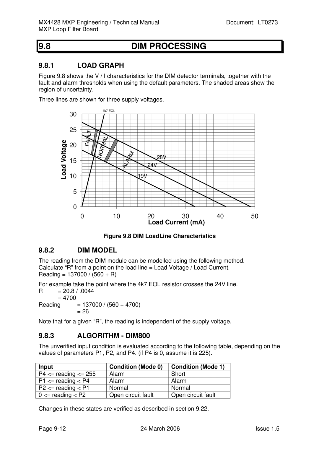
Load Graph
Input Condition Mode
DIM Processing
DIM Model
RIM Processing
SNM Processing
ELD and Position Monitoring
LPS Processing
VLC800 Processing
Correct Relay Position AI0, AI1 Condition
Filter Step Limits
Zone Alarm Test
Zone Fault Test
Autotest and System Test
Fast Point Test
NON Latching Test Mode
Commission Mode
Slow Point Test
Ancillary Filtering
Test Modes Summary
Reset of DIM Module
23RESET
Reset of Addressable Detector
Reset of Ancillary Input Device
Device Initialisation and Polling
Version Features
Software Versions
Chapter MXP Loop Filter Board
USE of MXP Loop Filter Board
10.2FITTING
10.3DIAGNOSTICS
This page Intentionally Left Blank