24 and 16 Port Smart Switch II – User Manual | Page 4 |
Front Panel
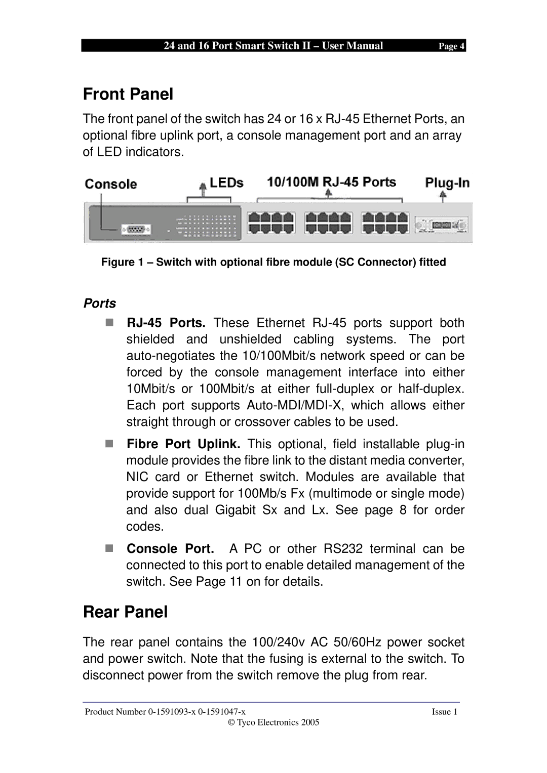
The front panel of the switch has 24 or 16 x RJ-45 Ethernet Ports, an optional fibre uplink port, a console management port and an array of LED indicators.
Figure 1 – Switch with optional fibre module (SC Connector) fitted
Ports
!RJ-45 Ports. These Ethernet RJ-45 ports support both shielded and unshielded cabling systems. The port auto-negotiates the 10/100Mbit/s network speed or can be forced by the console management interface into either 10Mbit/s or 100Mbit/s at either full-duplex or half-duplex. Each port supports Auto-MDI/MDI-X, which allows either straight through or crossover cables to be used.
!Fibre Port Uplink. This optional, field installable plug-in module provides the fibre link to the distant media converter, NIC card or Ethernet switch. Modules are available that provide support for 100Mb/s Fx (multimode or single mode) and also dual Gigabit Sx and Lx. See page 8 for order codes.
!Console Port. A PC or other RS232 terminal can be connected to this port to enable detailed management of the switch. See Page 11 on for details.
Rear Panel
The rear panel contains the 100/240v AC 50/60Hz power socket and power switch. Note that the fusing is external to the switch. To disconnect power from the switch remove the plug from rear.
Product Number 0-1591093-x 0-1591047-x | Issue 1 |
© Tyco Electronics 2005 | |

