CLR2060 — Clear Ice Maker | ™ |
| |
|
|
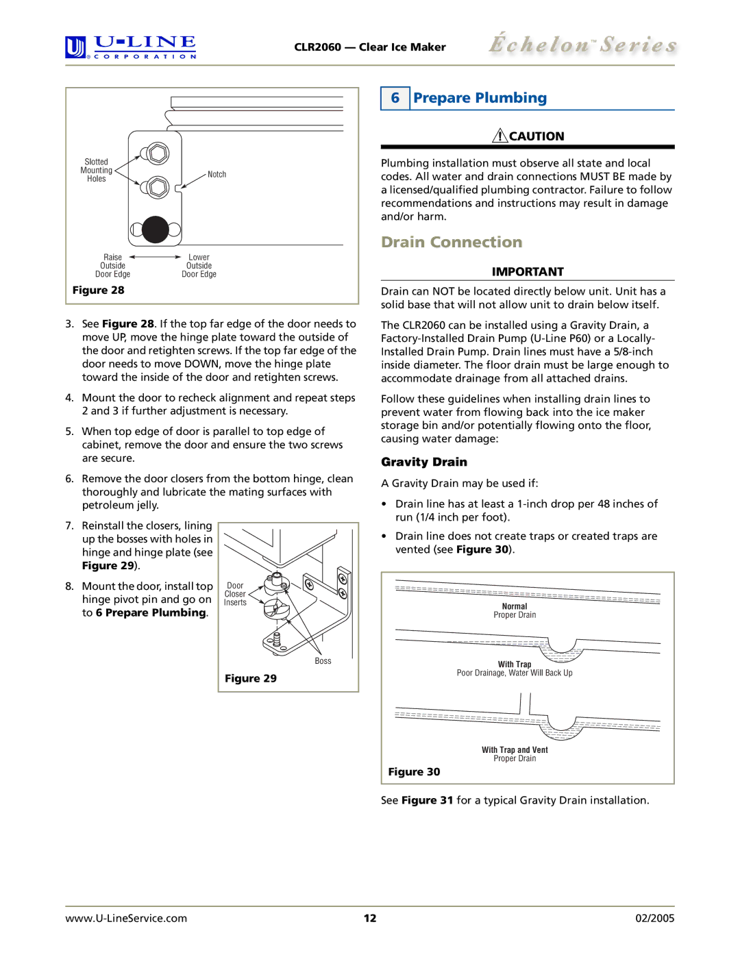
Slotted |
| |
Mounting | Notch | |
Holes | ||
| ||
Raise | Lower | |
Outside | Outside | |
Door Edge | Door Edge | |
Figure 28 |
|
3.See Figure 28. If the top far edge of the door needs to move UP, move the hinge plate toward the outside of the door and retighten screws. If the top far edge of the door needs to move DOWN, move the hinge plate toward the inside of the door and retighten screws.
4.Mount the door to recheck alignment and repeat steps 2 and 3 if further adjustment is necessary.
5.When top edge of door is parallel to top edge of cabinet, remove the door and ensure the two screws are secure.
6.Remove the door closers from the bottom hinge, clean thoroughly and lubricate the mating surfaces with petroleum jelly.
6 Prepare Plumbing
![]() CAUTION
CAUTION
Plumbing installation must observe all state and local codes. All water and drain connections MUST BE made by a licensed/qualified plumbing contractor. Failure to follow recommendations and instructions may result in damage and/or harm.
Drain Connection
IMPORTANT
Drain can NOT be located directly below unit. Unit has a solid base that will not allow unit to drain below itself.
The CLR2060 can be installed using a Gravity Drain, a
Follow these guidelines when installing drain lines to prevent water from flowing back into the ice maker storage bin and/or potentially flowing onto the floor, causing water damage:
Gravity Drain
A Gravity Drain may be used if:
• Drain line has at least a |
run (1/4 inch per foot). |
7.Reinstall the closers, lining up the bosses with holes in hinge and hinge plate (see Figure 29).
8.Mount the door, install top hinge pivot pin and go on to 6 Prepare Plumbing.
Door |
Closer |
Inserts |
Boss |
Figure 29 |
• Drain line does not create traps or created traps are |
vented (see Figure 30). |
Normal |
Proper Drain |
With Trap |
Poor Drainage, Water Will Back Up |
With Trap and Vent |
Proper Drain |
Figure 30 |
See Figure 31 for a typical Gravity Drain installation.
12 | 02/2005 |
