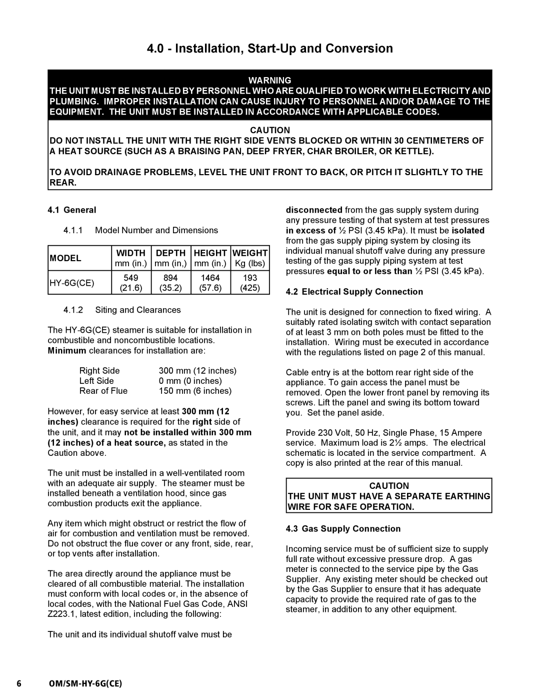
HY-6G(CE) specifications
Unified Brands HY-6G(CE) is a pioneering cooking solution in the commercial kitchen landscape, known for its exceptional performance, versatility, and cutting-edge technologies. Designed to meet the rigorous demands of foodservice establishments, the HY-6G(CE) excels at efficiently preparing a wide range of dishes while ensuring consistent quality and safety.One of the standout features of the HY-6G(CE) is its powerful heating capability. Equipped with advanced infrared heating technology, this unit delivers rapid and uniform heat distribution, making it ideal for both quick service and high-volume operations. The adjustable temperature controls allow chefs to fine-tune the cooking process, ensuring that every dish meets their exacting standards.
Another innovative aspect of the HY-6G(CE) is its energy efficiency. The incorporation of smart energy management systems ensures optimal power usage, reducing operational costs without sacrificing performance. The unit’s environmentally friendly design also aligns with sustainability initiatives, making it a responsible choice for modern kitchens.
The HY-6G(CE) boasts a user-friendly interface that facilitates ease of operation. Its digital display provides real-time feedback on cooking parameters, while programmable settings enable chefs to recall precise cooking profiles for various menu items. This feature not only streamlines kitchen workflow but also enhances productivity, allowing staff to focus on delivering exceptional customer service.
Durability is another hallmark of the HY-6G(CE). Constructed from high-quality stainless steel, it withstands the rigors of daily use in busy kitchens while resisting corrosion and wear. Its compact design allows for easy integration into existing kitchen layouts, making it an excellent option for both new builds and remodels.
Safety is paramount in any culinary environment, and the HY-6G(CE) addresses this with multiple safety features. These include automatic shut-off mechanisms and thermal protection systems that safeguard against overheating, ensuring secure operation even in the most demanding settings.
In summary, Unified Brands HY-6G(CE) stands out in the commercial cooking equipment market due to its blend of power, efficiency, and safety. With features that cater to the diverse needs of any foodservice establishment, it is an invaluable tool for chefs looking to elevate their culinary offerings while maintaining operational excellence. Whether in a bustling restaurant or a catering operation, the HY-6G(CE) is designed to deliver reliable and outstanding results.