®
DIRECT-VENT FIREPLACE
VENTING INSTALLATION
Continued
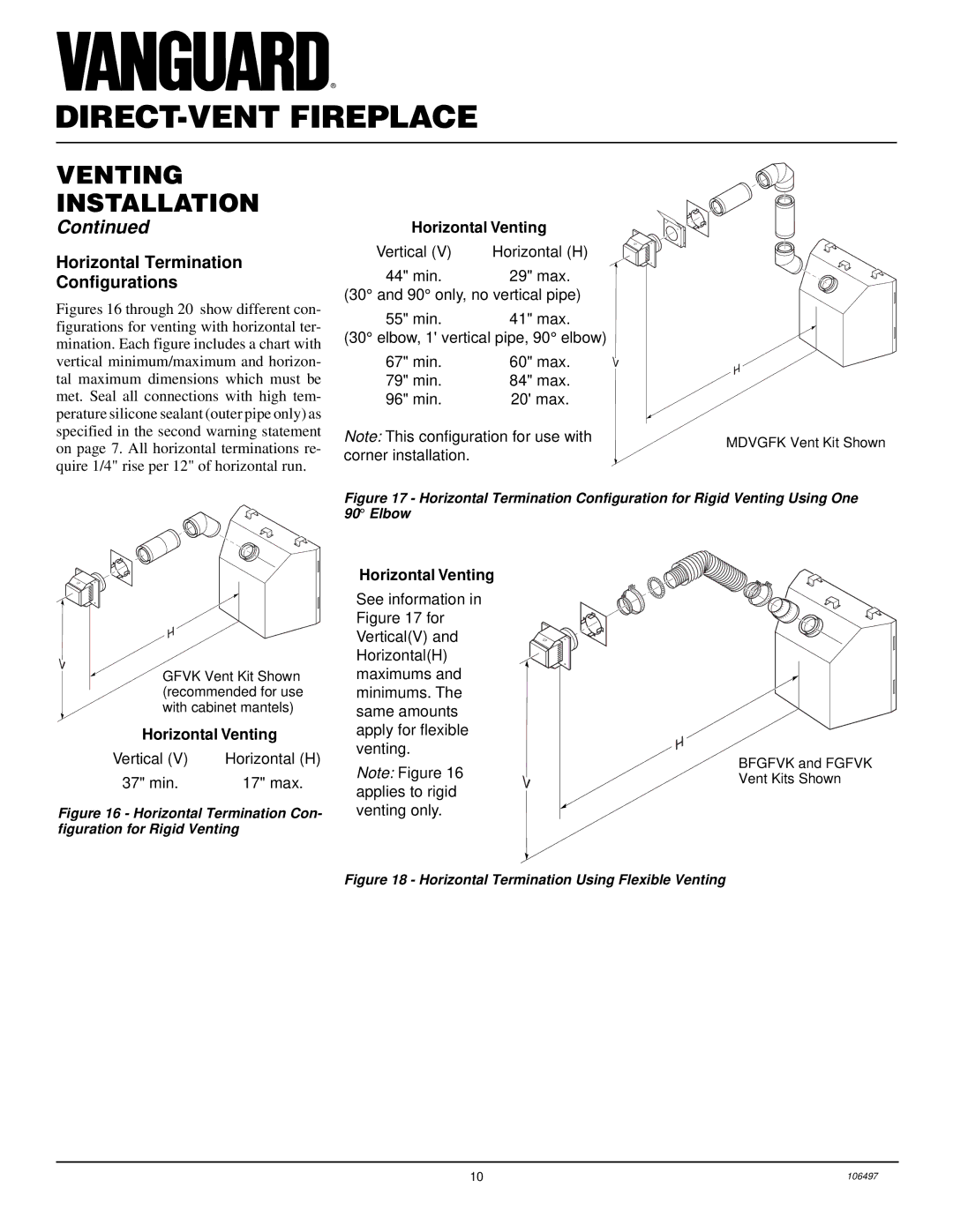
Horizontal Termination
Configurations
Figures 16 through 20 show different con- figurations for venting with horizontal ter- mination. Each figure includes a chart with vertical minimum/maximum and horizon- tal maximum dimensions which must be met. Seal all connections with high tem- perature silicone sealant (outer pipe only) as specified in the second warning statement on page 7. All horizontal terminations re- quire 1/4" rise per 12" of horizontal run.
Horizontal Venting
| UP |
|
Vertical (V) | Horizontal (H) |
|
| ||
44" min. | 29" max. |
|
(30° and 90° only, no vertical pipe) |
| |
55" min. | 41" max. |
|
(30° elbow, 1' vertical pipe, 90° elbow) |
| |
67" min. | 60" max. |
|
79" min. | 84" max. |
|
96" min. | 20' max. |
|
Note: This configuration for use with | MDVGFK Vent Kit Shown | |
corner installation. | ||
|
Figure 17 - Horizontal Termination Configuration for Rigid Venting Using One 90° Elbow
UP
GFVK Vent Kit Shown (recommended for use with cabinet mantels)
Horizontal Venting
Vertical (V) | Horizontal (H) |
37" min. | 17" max. |
Figure 16 - Horizontal Termination Con- figuration for Rigid Venting
Horizontal Venting
See information in Figure 17 for Vertical(V) and Horizontal(H) maximums and minimums. The same amounts apply for flexible venting.
Note: Figure 16 applies to rigid venting only.
UP
BFGFVK and FGFVK Vent Kits Shown
Figure 18 - Horizontal Termination Using Flexible Venting
10 | 106497 |