®
DIRECT-VENT FIREPLACE
INSTALLATION INSTRUCTIONS FOR CONVERSION NATURAL TO PROPANE/LP
Continued
7.Remove the burner by loosening the two 5/16" hex mounting screws (see Figure 62). Lift burner up and out.
8.Convert the pilot burner by changing out the pilot orifice. Remove the compres- sion nut and compression sleeve from the pilot. Remove the pilot orifice from inside the pilot barrel (see Figure 63). Replace with the pilot orifice supplied with the fireplace. Note: The new pilot orifice has the number 30 stamped on it for identification purposes.
9.Place open end of pilot orifice on top of compression sleeve and carefully slide up inside pilot burner. Tighten compres- sion nut (see Figure 63). IMPORTANT: Be careful not to bend or kink alumi- num tubing during conversion. Make sure the compression sleeve and pilot orifice are properly mated and aligned before retightening the compression nut.
Main Burner
Orifice (18mm
Hex)
Apply Thread
Sealant Here
Only
Brass Elbow
Figure 62 - Removing/Replacing Main Burner Orifice
10.Adjust air shutter setting on main burner. Loosen air shutter screw and rotate air shutter to FULLY OPEN po- sition (see Figure 61, page 29). Tighten shutter screw. Place burner back into position. Attach with the two 5/16" hex mounting screws removed in step 5.
11.Attach main burner orifice and brass elbow assembly to burner. Place main burner orifice into threaded end of burner and turn clockwise to tighten (see Figure 61, page 29). Align the brass elbow with the flare fitting on the alu- minum tubing.
12.Reconnect the aluminum tube flare fit- ting onto the brass elbow (see Figure 61, page 29).
13.Reapply RTV silicone to seal area where orifice passes through the bottom com- bustion chamber (see Figure 61, page 29).
Thermopile
Pilot Burner
Piezo Ignitor
Thermocouple
12mm ![]() Hex
Hex
Pilot Orifice
Compression
Sleeve
Compression Nut
(10mm Hex)
Figure 63 - Removing/Replacing Pilot Orifice
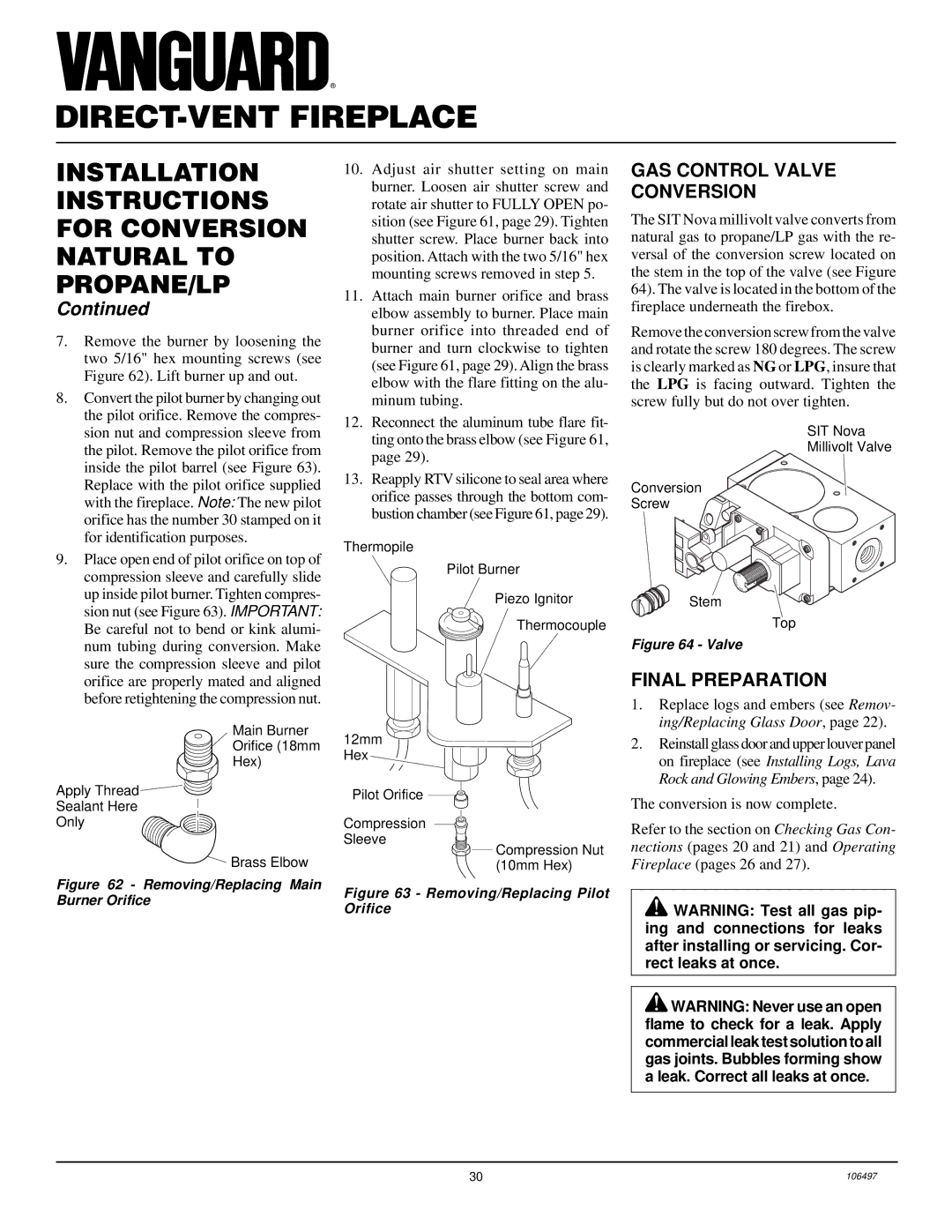
GAS CONTROL VALVE CONVERSION
The SIT Nova millivolt valve converts from natural gas to propane/LP gas with the re- versal of the conversion screw located on the stem in the top of the valve (see Figure 64). The valve is located in the bottom of the fireplace underneath the firebox.
Remove the conversion screw from the valve and rotate the screw 180 degrees. The screw is clearly marked as NG or LPG, insure that the LPG is facing outward. Tighten the screw fully but do not over tighten.
SIT Nova
Millivolt Valve
Conversion
Screw
ON
T
O
L
I
P
OFF
Stem
Top
Figure 64 - Valve
FINAL PREPARATION
1.Replace logs and embers (see Remov- ing/Replacing Glass Door, page 22).
2.Reinstall glass door and upper louver panel on fireplace (see Installing Logs, Lava Rock and Glowing Embers, page 24).
The conversion is now complete.
Refer to the section on Checking Gas Con- nections (pages 20 and 21) and Operating Fireplace (pages 26 and 27).
![]() WARNING: Test all gas pip- ing and connections for leaks after installing or servicing. Cor- rect leaks at once.
WARNING: Test all gas pip- ing and connections for leaks after installing or servicing. Cor- rect leaks at once.
![]() WARNING: Never use an open flame to check for a leak. Apply commercial leak test solution to all gas joints. Bubbles forming show a leak. Correct all leaks at once.
WARNING: Never use an open flame to check for a leak. Apply commercial leak test solution to all gas joints. Bubbles forming show a leak. Correct all leaks at once.
30 | 106497 |