OWNER’S MANUAL
FIREPLACE INSTALLATION
Continued
BLOWER ASSEMBLY AND OPERATION
Note: The blower is preinstalled in this fireplace. Verify blower assembly place- ment was not altered during shipping and speed control is mounted to bracket.
NOTICE: If installing blower in an existing fireplace with gas con- nections, shut off gas supply and disconnect heater from gas sup- ply. Contact a qualified service person to do this.
Installing GA3700 Blower
(Some Models Have Blower Assembly Preinstalled)
IMPORTANT: For clarity, gas valve assem- bly and grate/burner assembly are not shown in Figures 31 through 33. They will, how- ever, be in your fireplace when you are in- stalling the blower. Also for clarity the fire- box is shown with dotted lines.
1.Open lower louver panel or remove for easier access.
2.Place the blower against the lower rear wall of firebox outer wrapper with the exhaust port directed upward. Align the holes in the top mounting tabs of blower with holes in wall of wrapper (see Figure 31). Using the two screws provided, mount blower and tighten screws securely.
3.Be sure to securely attach all wire ter- minals to terminals on blower motor and that the screw retaining the green ground wire is tight.
4.Remove screws securing the plate con- taining the ON/OFF switch to the bot- tom of the firebox and set aside.
5.Place speed control against back of this plate and push the plastic control shaft through opening (see Figure 32).
6.While supporting speed control, secure con- trol shaft with lock nut by pushing and turn- ing lock nut with pliers clockwise until tight against the plate. Place control knob pro- vided onto shaft (see Figure 32).
7.Replace plate containing switches and tighten screws securely.
8.Plug in blower power cord.
a.If your fireplace system is installed as a freestanding unit with an ac- cessory mantel, determine whether the power cord will exit the left side or the right side of the firebox. In- stall one plastic bushing provided into the 1 1/2" hole in the outer cas- ing through which the power cord will exit. Install the second plastic bushing provided into the floor sup- port bracket if exiting through the right side (see Figure 33). Route power cord through (both) plastic bushing(s) and plug the power cord into a properly grounded
b.If your fireplace system installation is recessed and/or
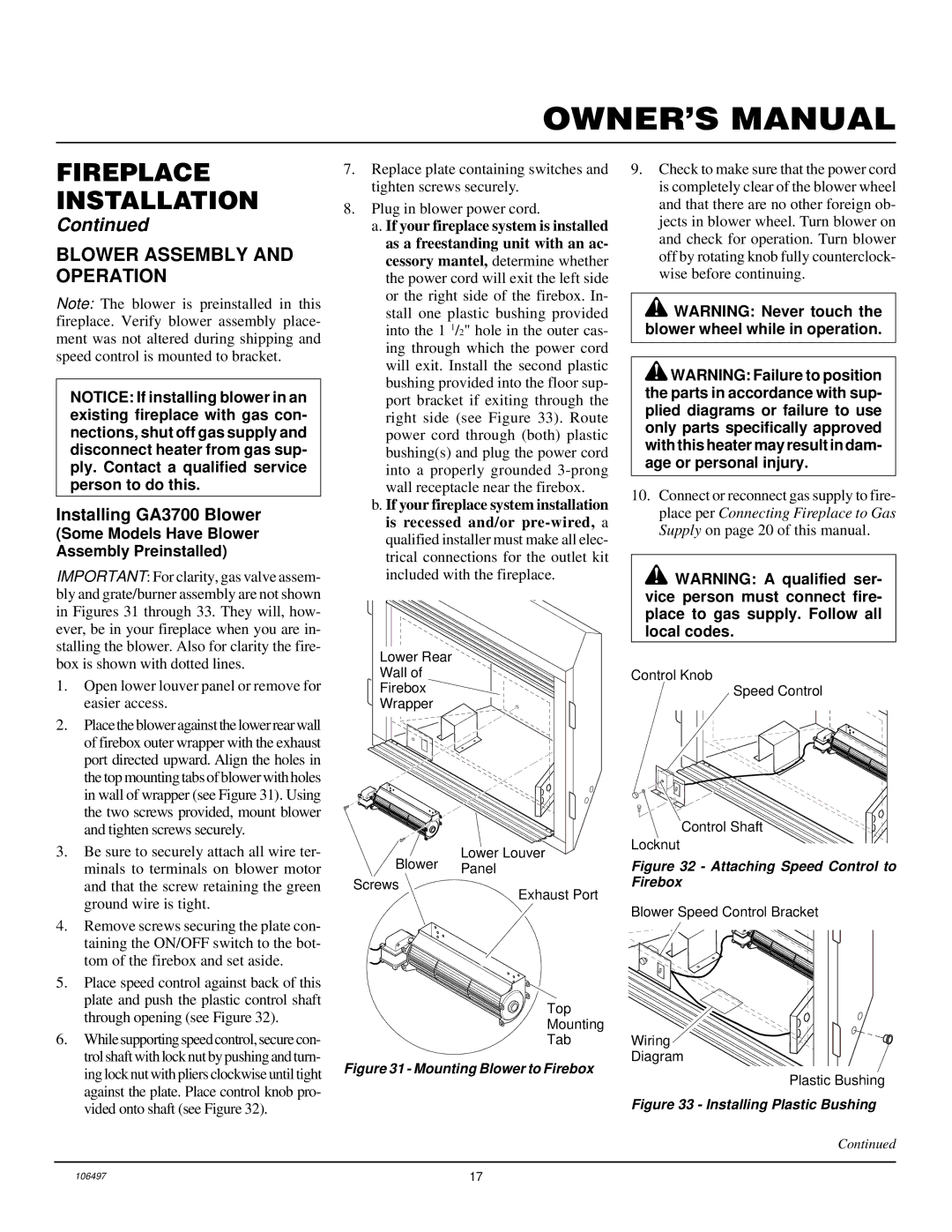
Lower Rear
Wall of
Firebox ![]()
Wrapper
Lower Louver
Blower Panel
Screws
Exhaust Port
Top
Mounting
Tab
Figure 31 - Mounting Blower to Firebox
9.Check to make sure that the power cord is completely clear of the blower wheel and that there are no other foreign ob- jects in blower wheel. Turn blower on and check for operation. Turn blower off by rotating knob fully counterclock- wise before continuing.
![]() WARNING: Never touch the blower wheel while in operation.
WARNING: Never touch the blower wheel while in operation.
![]() WARNING: Failure to position the parts in accordance with sup- plied diagrams or failure to use only parts specifically approved with this heater may result in dam- age or personal injury.
WARNING: Failure to position the parts in accordance with sup- plied diagrams or failure to use only parts specifically approved with this heater may result in dam- age or personal injury.
10.Connect or reconnect gas supply to fire- place per Connecting Fireplace to Gas Supply on page 20 of this manual.
![]() WARNING: A qualified ser- vice person must connect fire- place to gas supply. Follow all local codes.
WARNING: A qualified ser- vice person must connect fire- place to gas supply. Follow all local codes.
Control Knob
Speed Control
Control Shaft
Locknut
Figure 32 - Attaching Speed Control to Firebox
Blower Speed Control Bracket
Wiring
Diagram
Plastic Bushing
Figure 33 - Installing Plastic Bushing
Continued
106497 | 17 |