®
DIRECT-VENT FIREPLACE
VENTING INSTALLATION
Continued
Installing Vent System in a Chase
A chase is a vertical boxlike structure built to enclose venting that runs along the out- side of a building. A chase is not required for such venting.
NOTICE: Treatment of firestops and construction of the chase may vary from building type to build- ing type. These instructions are not substitutes for the require- ments of local building codes. You must follow all local building codes .
Note: When installing in a chase, you should insulate the chase as you would the outside walls of your home. This is especially im- portant in cold climates. Minimum clear- ance between vent pipes and combustible materials such as insulation is 1".
After framing the chase (see Framing and Finishing on pages 4 and 5) install the vent system by following the installation instructions.
INSTALLATION FOR HORIZONTAL TERMINATION
2.Rigid vent pipes and fittings have spe- cial
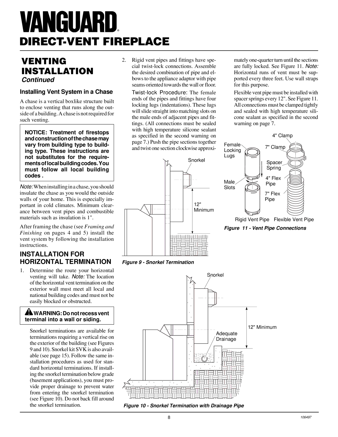
Snorkel |
12" |
Minimum |
Figure 9 - Snorkel Termination
mately
Flexible vent pipe must be installed with spacer springs every 12". See Figure 11. All connections must be clamped tightly and sealed with high temperature sili- cone sealant as specified in the second warning on page 7.
| 4" Clamp | |
Female | 7" Clamp | |
Locking | ||
| ||
Lugs |
| |
| Spacer | |
| Spring | |
Male | 4" Flex | |
Pipe | ||
Slots | ||
| ||
| 7" Flex | |
| Pipe | |
Rigid Vent Pipe Flexible Vent Pipe | ||
Figure 11 - Vent Pipe Connections
1.Determine the route your horizontal venting will take. Note: The location of the horizontal vent termination on the exterior wall must meet all local and national building codes and must not be easily blocked or obstructed.
![]() WARNING: Do not recess vent terminal into a wall or siding.
WARNING: Do not recess vent terminal into a wall or siding.
Snorkel terminations are available for terminations requiring a vertical rise on the exterior of the building (see Figures 9 and 10). Snorkel kit SVK is also avail- able (see page 15). Follow the same in- stallation procedures as used for stan- dard horizontal terminations. If install- ing the snorkel termination below grade (basement applications), you must pro- vide proper drainage to prevent water from entering the snorkel termination (see Figure 10). Do not back fill around the snorkel termination.
Snorkel
12" Minimum
Adequate
Drainage
Figure 10 - Snorkel Termination with Drainage Pipe
8 | 106497 |