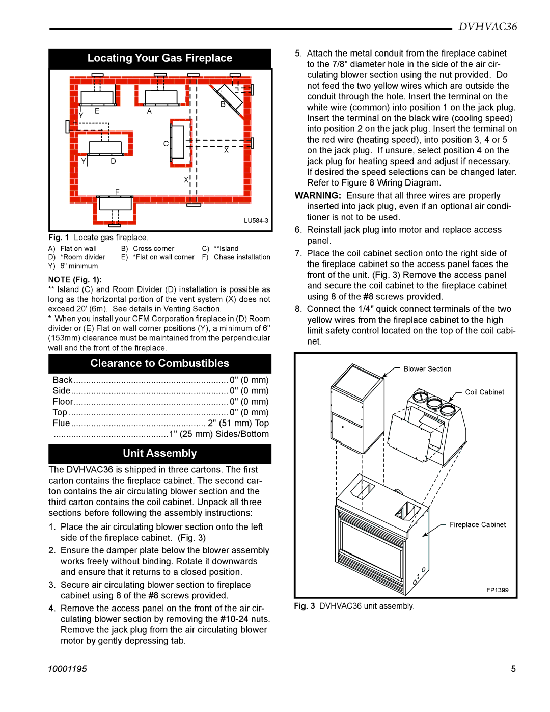
Locating Your Gas Fireplace
|
| E | A | B |
| Y |
| ||
|
|
|
| |
|
|
| C | X |
| Y |
| D | |
|
|
| ||
|
|
|
| X |
|
|
| F |
|
|
|
|
| |
Fig. 1 | Locate gas fireplace. |
| ||
A) | Flat on wall | B) | Cross corner | C) | **Island |
D) | *Room divider | E) | *Flat on wall corner | F) | Chase installation |
Y) | 6" minimum |
|
|
|
|
NOTE (Fig. 1):
**Island (C) and Room Divider (D) installation is possible as long as the horizontal portion of the vent system (X) does not exceed 20' (6m). See details in Venting Section.
* When you install your CFM Corporation fireplace in (D) Room divider or (E) Flat on wall corner positions (Y), a minimum of 6" (153mm) clearance must be maintained from the perpendicular wall and the front of the fireplace.
Clearance to Combustibles
Back | .............................................................. 0" (0 mm) |
Side | 0" (0 mm) |
Floor | .............................................................. 0" (0 mm) |
Top | 0" (0 mm) |
Flue | 2" (51 mm) Top |
.............................................. | 1" (25 mm) Sides/Bottom |
Unit Assembly
The DVHVAC36 is shipped in three cartons. The first carton contains the fireplace cabinet. The second car- ton contains the air circulating blower section and the third carton contains the coil cabinet. Unpack all three sections before following the assembly instructions:
1.Place the air circulating blower section onto the left side of the fireplace cabinet. (Fig. 3)
2.Ensure the damper plate below the blower assembly works freely without binding. Rotate it downwards and ensure that it returns to a closed position.
3.Secure air circulating blower section to fireplace cabinet using 8 of the #8 screws provided.
4.Remove the access panel on the front of the air cir- culating blower section by removing the
DVHVAC36
5.Attach the metal conduit from the fireplace cabinet to the 7/8" diameter hole in the side of the air cir- culating blower section using the nut provided. Do not feed the two yellow wires which are outside the conduit through the hole. Insert the terminal on the white wire (common) into position 1 on the jack plug. Insert the terminal on the black wire (cooling speed) into position 2 on the jack plug. Insert the terminal on the red wire (heating speed), into position 3, 4 or 5 on the jack plug. If unsure, select position 4 on the jack plug for heating speed and adjust if necessary. If desired the speed selections can be changed later. Refer to Figure 8 Wiring Diagram.
WARNING: Ensure that all three wires are properly inserted into jack plug, even if an optional air condi- tioner is not to be used.
6.Reinstall jack plug into motor and replace access panel.
7.Place the coil cabinet section onto the right side of the fireplace cabinet so the access panel faces the front of the unit. (Fig. 3) Remove the access panel and secure the coil cabinet to the fireplace cabinet using 8 of the #8 screws provided.
8.Connect the 1/4" quick connect terminals of the two yellow wires from the fireplace cabinet to the high limit safety control located on the top of the coil cabi- net.
Blower Section
Coil Cabinet
Fireplace Cabinet
FP1399
Fig. 3 DVHVAC36 unit assembly.
10001195 | 5 |