DVHVAC36
General Venting Information - Termination Location
D
E
V
L
![]() B
B![]()
CFM145a
![]() C
C![]()
V�����
������
F | V | Operable |
|
![]() B
B![]()
| INSIDE |
|
|
| |
| CORNER DETAIL |
|
|
| |
| G |
|
|
|
|
| V |
|
|
| N |
A |
|
| H | N | |
|
|
| |||
|
|
|
| ||
B |
|
|
|
|
|
V |
| B | V |
|
|
Operable | Fixed |
|
|
| |
| Closed |
|
|
| |
|
|
|
|
| |
| V J | B | M |
| |
B | X |
| |||
| V K X | ||||
| A |
| I |
| |
|
|
|
|
| |
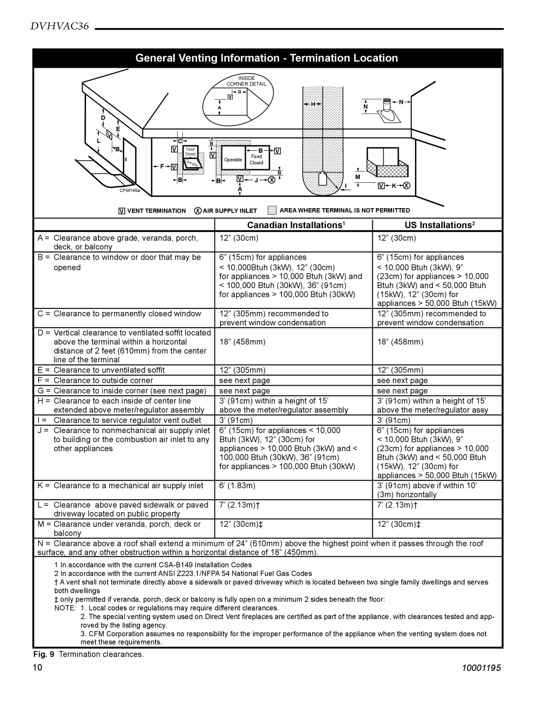
V VENT TERMINATION X AIR SUPPLY INLET ![]() AREA WHERE TERMINAL IS NOT PERMITTED
AREA WHERE TERMINAL IS NOT PERMITTED
|
|
| Canadian Installations1 | US Installations2 |
| A = | Clearance above grade, veranda, porch, | 12” (30cm) | 12” (30cm) |
|
| deck, or balcony |
|
|
| B = Clearance to window or door that may be | 6” (15cm) for appliances | 6” (15cm) for appliances | |
|
| opened | < 10,000Btuh (3kW), 12” (30cm) | < 10,000 Btuh (3kW), 9” |
|
|
| for appliances > 10,000 Btuh (3kW) and | (23cm) for appliances > 10,000 |
|
|
| < 100,000 Btuh (30kW), 36” (91cm) | Btuh (3kW) and < 50,000 Btuh |
|
|
| for appliances > 100,000 Btuh (30kW) | (15kW), 12” (30cm) for |
|
|
|
| appliances > 50,000 Btuh (15kW) |
| C = Clearance to permanently closed window | 12” (305mm) recommended to | 12” (305mm) recommended to | |
|
|
| prevent window condensation | prevent window condensation |
| D = Vertical clearance to ventilated soffit located |
|
| |
|
| above the terminal within a horizontal | 18” (458mm) | 18” (458mm) |
|
| distance of 2 feet (610mm) from the center |
|
|
|
| line of the terminal |
|
|
| E = Clearance to unventilated soffit | 12” (305mm) | 12” (305mm) | |
| F = | Clearance to outside corner | see next page | see next page |
| G = Clearance to inside corner (see next page) | see next page | see next page | |
| H = Clearance to each inside of center line | 3’ (91cm) within a height of 15’ | 3’ (91cm) within a height of 15’ | |
|
| extended above meter/regulator assembly | above the meter/regulator assembly | above the meter/regulator assy |
| I = | Clearance to service regulator vent outlet | 3’ (91cm) | 3’ (91cm) |
| J = | Clearance to nonmechanical air supply inlet | 6” (15cm) for appliances < 10,000 | 6” (15cm) for appliances |
|
| to building or the combustion air inlet to any | Btuh (3kW), 12” (30cm) for | < 10,000 Btuh (3kW), 9” |
|
| other appliances | appliances > 10,000 Btuh (3kW) and < | (23cm) for appliances > 10,000 |
|
|
| 100,000 Btuh (30kW), 36” (91cm) | Btuh (3kW) and < 50,000 Btuh |
|
|
| for appliances > 100,000 Btuh (30kW) | (15kW), 12” (30cm) for |
|
|
|
| appliances > 50,000 Btuh (15kW) |
| K = | Clearance to a mechanical air supply inlet | 6’ (1.83m) | 3’ (91cm) above if within 10’ |
|
|
|
| (3m) horizontally |
| L = | Clearance above paved sidewalk or paved | 7’ (2.13m)† | 7’ (2.13m)† |
|
| driveway located on public property |
|
|
| M = Clearance under veranda, porch, deck or | 12” (30cm)‡ | 12” (30cm)‡ | |
|
| balcony |
|
|
N = Clearance above a roof shall extend a minimum of 24” (610mm) above the highest point when it passes through the roof surface, and any other obstruction within a horizontal distance of 18” (450mm).
1 In accordance with the current
2 In accordance with the current ANSI Z223.1/NFPA 54 National Fuel Gas Codes
†A vent shall not terminate directly above a sidewalk or paved driveway which is located between two single family dwellings and serves both dwellings
‡ only permitted if veranda, porch, deck or balcony is fully open on a minimum 2 sides beneath the floor: NOTE: 1. Local codes or regulations may require different clearances.
2.The special venting system used on Direct Vent fireplaces are certified as part of the appliance, with clearances tested and app- roved by the listing agency.
3.CFM Corporation assumes no responsibility for the improper performance of the appliance when the venting system does not meet these requirements.
Fig. 9 Termination clearances.
10 | 10001195 |