of coils be used with this product. When using 4" or 5" (102 or 127 mm) diameter duct work, the maximum air conditioning system size should be limited to 1.5 tons (18,000 BtuH). When using 6" (152 mm) diameter duct, air conditioners of up to 2 tons (24,000 BtuH) may be used. Total static pressure of the system above the out- let from the fireplace cabinet should not exceed 0.40" w.c. with the air circulating blower on high speed, when using the maximum air conditioning capacity.
Two rails come factory mounted in the coil cabinet. These represent the minimum clearance between the evaporator coil and the fireplace cabinet top. Do not mount an evaporator coil below the level of the rails.
Final Finishing
Noncombustible materials such as brick and tile can be extended over the front face of the unit (Do not cover louvres or glass door). If a trim kit is going to be installed, brick and tile will have to be installed flush with the side of this appliance.
Hearth
A hearth is not mandatory, however it is recommended for aesthetic purposes. We recommend a noncombus- tible hearth which projects out 12" (305 mm) or more in front of this unit.
Cold climate installation recommendation: When installing this unit against a non- insulated exterior wall or chase, it is mandatory the outer walls be insulated to conform to applicable insulation codes.
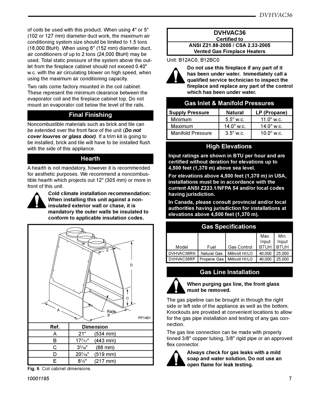
E
D
C
A | Rails |
|
| B | FP1401 |
|
| |
Ref. | Dimension |
|
A21" (534 mm)
B 17⁷⁄₁₇" (443 mm)
C 3⁷⁄₁₆" (88 mm)
D 20⁷⁄₁₆" (519 mm)
E8¹⁄₂" (217 mm)
Fig. 6 Coil cabinet dimensions.
DVHVAC36
DVHVAC36
Certified to
ANSI
Vented Gas Fireplace Heaters
Unit: B12AC0, B12BC0
Do not use this fireplace if any part of it has been under water. Immediately call a qualified service technician to inspect the fireplace and replace any part of the control which has been under water.
Gas Inlet & Manifold Pressures
Supply Pressure | Natural | LP (Propane) |
Minimum | 5.5" w.c. | 11.0" w.c. |
Maximum | 14.0" w.c. | 14.0" w.c. |
Manifold Pressure | 3.5" w.c. | 10.0" w.c. |
|
|
|
High Elevations
Input ratings are shown in BTU per hour and are certified without deration for elevations up to 4,500 feet (1,370 m) above sea level.
For elevations above 4,500 feet (1,370 m) in USA, installations must be in accordance with the current ANSI Z223.1/NFPA 54 and/or local codes having jurisdiction.
In Canada, please consult provincial and/or local authorities having jurisdiction for installations at elevations above 4,500 feet (1,370 m).
Gas Specifications
|
|
| Max. | Min. |
|
|
| Input | Input |
Model | Fuel | Gas Control | BTUH | BTUH |
DVHVAC36RN | Natural Gas | Millivolt HI/LO | 40,000 | 25,000 |
DVHVAC36RP | Propane Gas | Millivolt HI/LO | 40,000 | 25,000 |
|
|
|
|
|
Gas Line Installation
When purging gas line, the front glass must be removed.
The gas pipeline can be brought in through the right side or left side of the appliance as well as the bottom. Knockouts are provided at convenient locations to allow for the gas pipe installation and testing of any gas con- nection.
The gas line connection can be made with properly tinned 3/8" copper tubing, 3/8" rigid pipe or an approved flex connector.
Always check for gas leaks with a mild soap and water solution. Do not use an open flame for leak testing.
10001195 | 7 |