DVHVAC36
Framing and Finishing
1.Choose fireplace location.
2.Place fireplace into position and secure to floor with
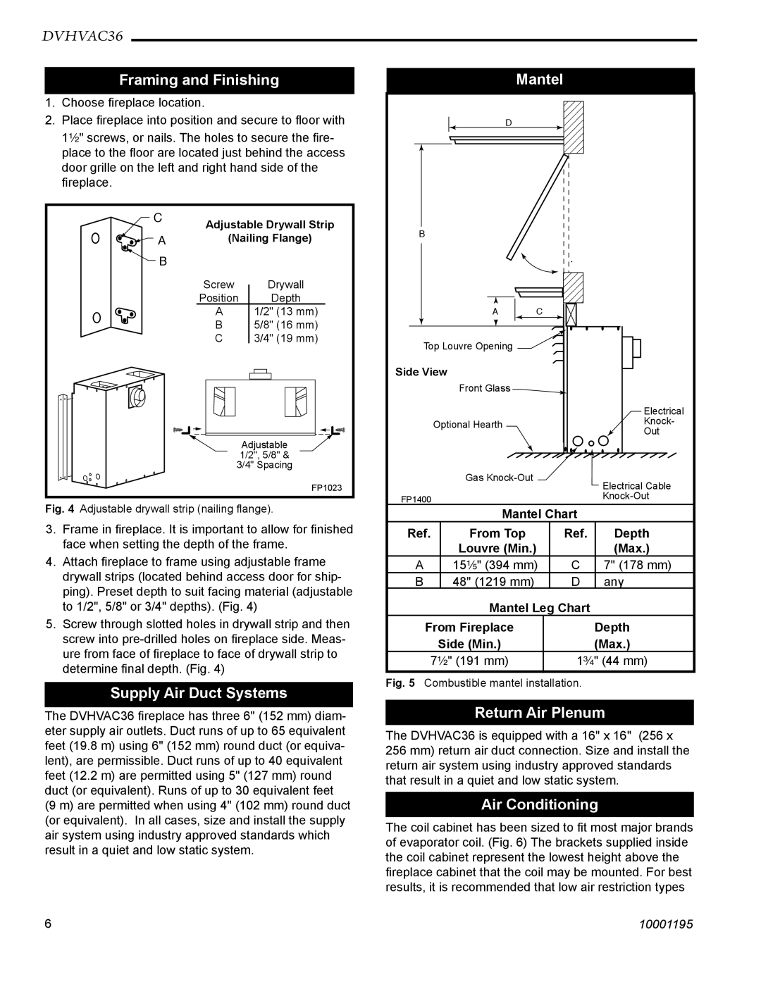
1¹⁄₂" screws, or nails. The holes to secure the fire- place to the floor are located just behind the access door grille on the left and right hand side of the fireplace.
C | Adjustable Drywall Strip | |
| ||
A | (Nailing Flange) | |
B |
|
|
| Screw | Drywall |
| Position | Depth |
| A | 1/2" (13 mm) |
| B | 5/8" (16 mm) |
| C | 3/4" (19 mm) |
|
| Adjustable |
|
| 1/2", 5/8" & |
| 3/4" Spacing | |
|
| FP1023 |
Fig. 4 Adjustable drywall strip (nailing flange). | ||
3.Frame in fireplace. It is important to allow for finished face when setting the depth of the frame.
4.Attach fireplace to frame using adjustable frame drywall strips (located behind access door for ship- ping). Preset depth to suit facing material (adjustable to 1/2", 5/8" or 3/4" depths). (Fig. 4)
5.Screw through slotted holes in drywall strip and then screw into
Supply Air Duct Systems
The DVHVAC36 fireplace has three 6" (152 mm) diam- eter supply air outlets. Duct runs of up to 65 equivalent feet (19.8 m) using 6" (152 mm) round duct (or equiva- lent), are permissible. Duct runs of up to 40 equivalent feet (12.2 m) are permitted using 5" (127 mm) round duct (or equivalent). Runs of up to 30 equivalent feet (9 m) are permitted when using 4" (102 mm) round duct (or equivalent). In all cases, size and install the supply air system using industry approved standards which result in a quiet and low static system.
| Mantel |
|
| |
| D |
|
|
|
B |
|
|
|
|
| A | C |
|
|
Top Louvre Opening |
|
|
| |
Side View |
|
|
| |
| Front Glass |
|
|
|
|
|
|
| Electrical |
| Optional Hearth |
|
| Knock- |
|
|
| Out | |
|
|
|
| |
| Gas |
|
| Electrical Cable |
|
|
|
| |
FP1400 |
|
|
| |
|
|
|
| |
| Mantel Chart |
| ||
Ref. | From Top |
| Ref. | Depth |
| Louvre (Min.) |
| (Max.) | |
A | 15¹⁄₅" (394 mm) | C | 7" (178 mm) | |
B | 48" (1219 mm) |
| D | any |
| Mantel Leg Chart |
| ||
From Fireplace |
|
| Depth | |
| Side (Min.) |
|
| (Max.) |
7¹⁄₂" (191 mm) |
| 1³⁄₄" (44 mm) | ||
Fig. 5 Combustible mantel installation.
Return Air Plenum
The DVHVAC36 is equipped with a 16" x 16" (256 x 256 mm) return air duct connection. Size and install the return air system using industry approved standards that result in a quiet and low static system.
Air Conditioning
The coil cabinet has been sized to fit most major brands of evaporator coil. (Fig. 6) The brackets supplied inside the coil cabinet represent the lowest height above the fireplace cabinet that the coil may be mounted. For best results, it is recommended that low air restriction types
6 | 10001195 |
