1
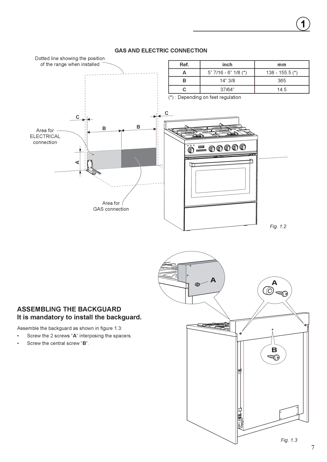
GAS AND ELECTRIC CONNECTION
Dotted line showing the position |
|
|
|
of the range when installed | Ref. | inch | mm |
| A | 5” 7/16 - 6” 1/8 (*) | 138 - 155.5 (*) |
| B | 14” 3/8 | 365 |
|
|
|
|
| C | 37/64” | 14.5 |
| (*) : Depending on feet regulation |
| |
C
Area for
ELECTRICAL connection
BB
C
A
Area for
GAS connection
Fig. 1.2
A
ASSEMBLING THE BACKGUARD
It is mandatory to install the backguard.
Assemble the backguard as shown in figure 1.3:
•Screw the 2 screws “A” interposing the spacers.
•Screw the central screw “B”.
A
B
Fig. 1.3
7
