1
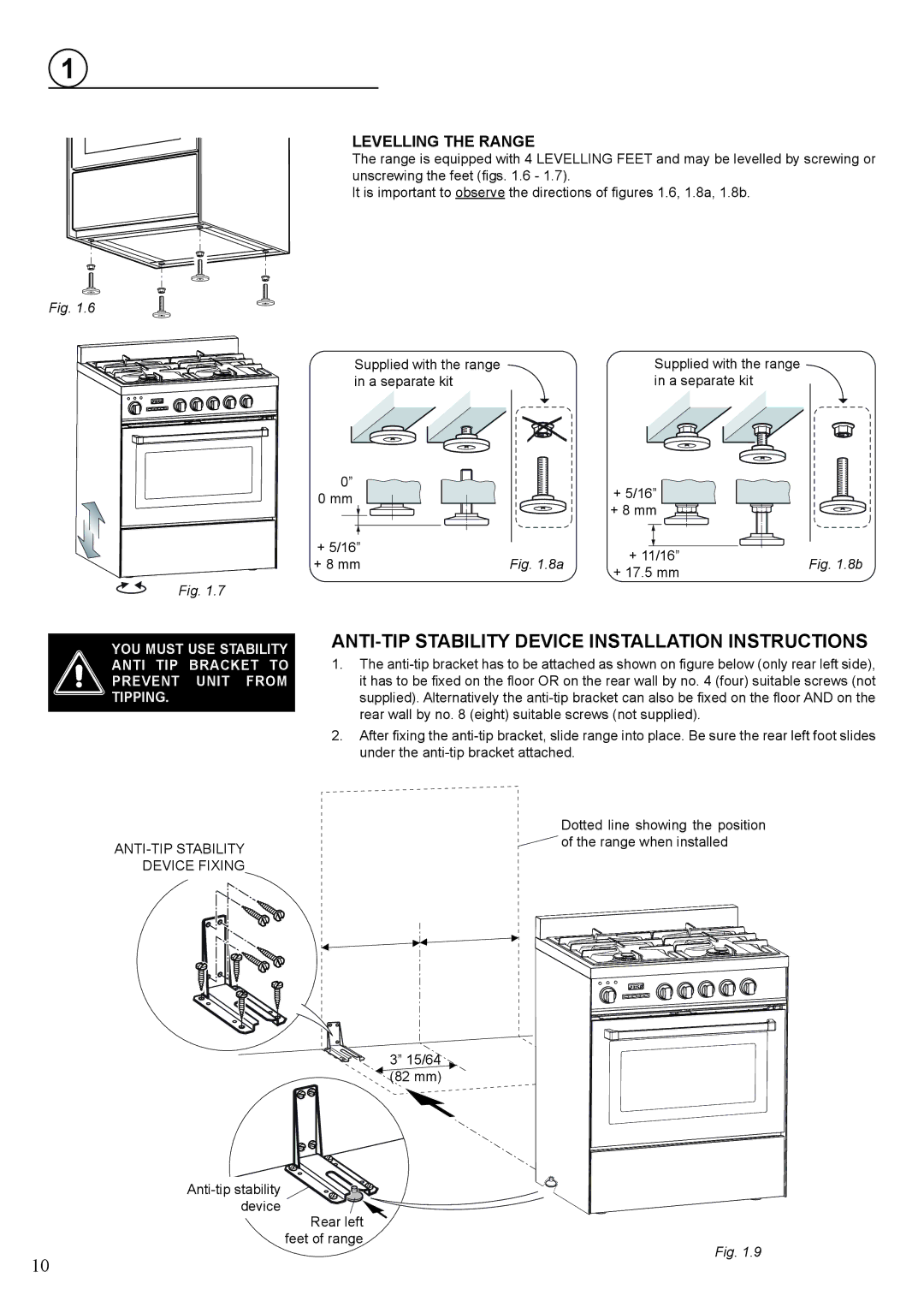
LEVELLING THE RANGE
The range is equipped with 4 LEVELLING FEET and may be levelled by screwing or unscrewing the feet (figs. 1.6 - 1.7).
It is important to observe the directions of figures 1.6, 1.8a, 1.8b.
Fig. 1.6
Supplied with the range |
| Supplied with the range |
in a separate kit |
| in a separate kit |
|
|
|
|
|
|
|
| 0” |
| + 5/16” |
|
|
| 0 mm |
|
| |
|
|
| + 8 mm |
| |
|
|
|
|
| |
|
| + 5/16” |
| + 11/16” |
|
|
| + 8 mm | Fig. 1.8a | Fig. 1.8b | |
|
| + 17.5 mm | |||
|
|
|
|
| |
Fig. 1.7 |
|
|
|
| |
YOU MUST USE STABILITY |
| ||||
ANTI TIP | BRACKET TO | 1. The | |||
PREVENT | UNIT FROM | it has to be fixed on the floor OR on the rear wall by no. 4 (four) suitable screws (not | |||
TIPPING. |
| supplied). Alternatively the | |||
|
| rear wall by no. 8 (eight) suitable screws (not supplied). |
| ||
2.After fixing the
Dotted line showing the position
![]() of the range when installed
of the range when installed
DEVICE FIXING
3” 15/64 ![]() (82 mm)
(82 mm)
Rear left feet of range
10
Fig. 1.9