2
INJECTORS TABLE
|
| NOMINAL | REDUCED | LP/PROPANE | NATURAL GAS | |
|
| POWER | POWER | 11” W.C.P. | 4” W.C.P. | |
BURNERS | BTU/hr | BTU/hr | Ø injector | Ø injector | ||
[1/100 mm] | [1/100 mm] | |||||
|
|
|
| |||
Semirapid (SR) | 8000 | 1500 | 85 | 139 | ||
|
|
|
|
|
| |
Dual (D) | Inner crown | 2100 | 1000 | 42 (*) | 70 (*) | |
|
|
|
|
| ||
Inner & outer crown | 17000 | 6500 | 115 (**) | 200 (**) | ||
| ||||||
|
|
|
|
|
| |
(*) inner crown (“J2” in figure 2.9) (**) outer crown (“J3” in figure 2.9)
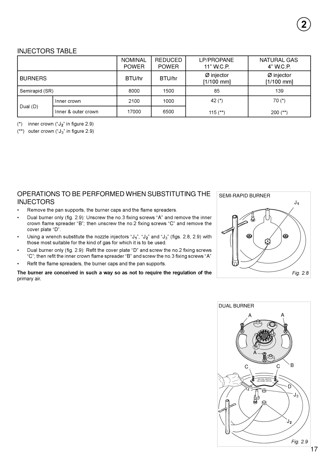
OPERATIONS TO BE PERFORMED WHEN SUBSTITUTING THE INJECTORS
•Remove the pan supports, the burner caps and the flame spreaders.
•Dual burner only (fig. 2.9): Unscrew the no.3 fixing screws “A” and remove the inner crown flame spreader “B”; then unscrew the no.2 fixing screws “C” and remove the cover plate “D”.
•Using a wrench substitute the nozzle injectors “J1”, “J2” and “J3” (figs. 2.8, 2.9) with those most suitable for the kind of gas for which it is to be used.
•Dual burner only (fig. 2.9): Refit the cover plate “D” and screw the no.2 fixing screws “C”; then refit the inner crown flame spreader “B” and screw the no.3 fixing screws “A”
•Refit the flame spreaders, the burner caps and the pan supports.
The burner are conceived in such a way so as not to require the regulation of the primary air.
J1 |
Fig. 2.8 |
DUAL BURNER |
|
|
A |
| A |
A |
|
|
C | C | B |
| SECOND ORIFICE |
|
| DEUXIEME ORIFICE |
|
|
| D |
|
| J3 |
|
| J2 |
|
| Fig. 2.9 |
|
| 17 |