Operating Manual
Contents
Introduction
Specifications
General
Transmitter
Receiver
Accessories & Options
Supplied Accessories
Available Options
Installation
Installation Tips
Preliminary Inspection
Safety Information
Installing the Microphone and Front Panel
Power Connections
MMB-82 Installation
Grounding
Mobile Station Grounding
Base Station Earth Grounding
Antenna Considerations
Mobile Antenna Installations
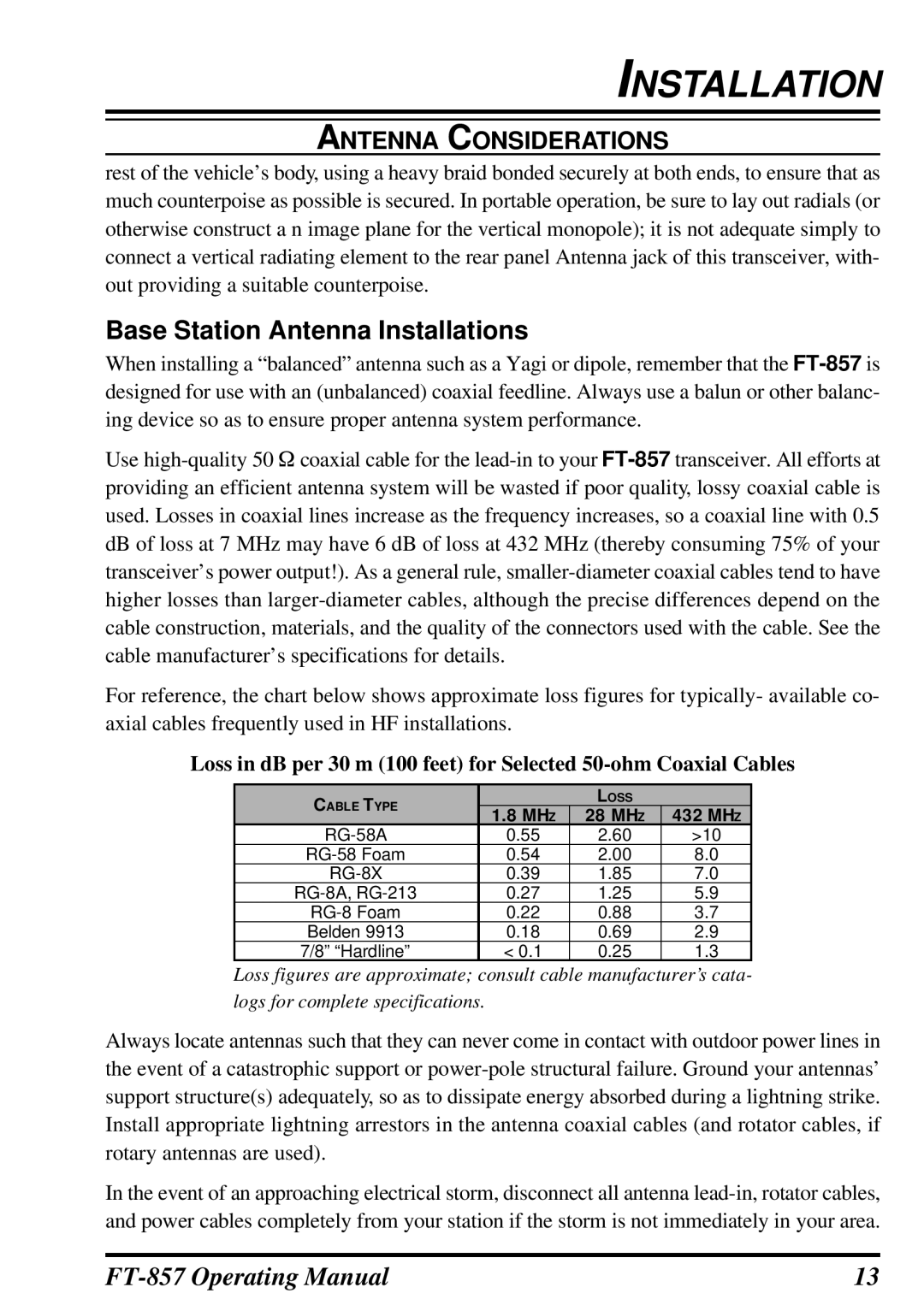
Base Station Antenna Installations
RF Field Exposure
Heat and Ventilation
Electromagnetic Compatibility
VHF or UHF amplifier
Linear Amplifier Interfacing
Important Note
CW KEY/KEYER Connections
Adjusting the Front Feet
Receiver Accessories Tape Recorder ETC
Installation
Front Panel Control & Switches
MODEt/MODEu Key
Power Switch
TX/BUSY Indicator
Func Key
BANDDWN/BANDUP Key
Key
Lock Key
SP/PH Jack
SP-PH Switch
MIC Jack
Meter Jack
Multi Function KEY Detail
Multi Function Row a MFa A/B, A=B, SPL
Multi Function Row b MFb MW, SKIP, TAG
Multi Function Row d MFd RPT, REV, VOX
Multi Function Row c MFc STO, RCL, Proc
Multi Function Row e MFe TON, - -, Tdch ENC, DEC, Tdch
Multi Function Row f MFf ARTS, SRCH, PMS
Multi Function Row g MFg SCN, PRI, DW
Multi Function Row i MFi MTR, - -, Disp
Multi Function Row h MFh SCOP, WID, Step
Multi Function Row j MFj SPOT, BK, KYR
Multi Function Row k MFk TUNE, DOWN, UP
Multi Function Row l MFl NB, AGC
Multi Function Row m MFm IPO, ATT, NAR
Multi Function Row n MFn Cfil
Multi Function Row o MFo PLY1, PLY2, PLY3
Multi Function Row q MFq MONI, QSPL, ATC Programmable Keys
Multi Function Row p MFp DNR, DNF, DBF
Front Panel Control & Switches
Rear Panel Connectors
Input Jack
CAT/LINEAR Jack
EXT Spkr Jack
Data Jack
ACC Jack
KEY Jack
Operating Band Selection
Mode Selection
Operation
Turning the Transceiver on and OFF
Menu Quick Start
Adjusting the Audio Volume Level
Setting the Operating Frequency
Stacked VFO System
Changing the Dial Speed
Locking Front Panel Controls
Receiver Accessories
Clarifier Receiver Incremental Tuning
If Shift
Noise Blanker
AGC Automatic Gain Control
ATT Front END Attenuator
IPO Intercept Point Optimization
DSP Bandpass Filter DBF Requires Optional DSP-2 Unit
DSP CW Peaking Filter DBF Requires Optional DSP-2 Unit
AM/FM Tuning Dial Operation
Automatic POWER-OFF Feature
Receiver Accessories
Basic Setup/Operation
Transmitter Operation
SSB/AM Transmission
VOX Operation
AF Speech Processor Operation
DSP Microphone Equalizer Requires Optional DSP-2 Unit
CW Transmission
Operation using Straight Key/External Keying Device
Transmitter Operation
Mode No-030 CW Speed
Using the Built-in Electronic Keyer
Transmitter Operation
FM Transmission
Press and hold in the a RPT key for one
Repeater Operation
Tone Search Scanning
Mode No-083 Tone Freq
DCS Search Scanning
DCS Operation
Split Tone Operation
Split Tone Frequency or DCS Code Setup
Arts Operation
Arts is easy to use
Arts Alert Beep Options
CW Identifier Setup
Rtty Radio TeleType Operation
Digital Mode Operation SSB-BASED Afsk
User Defined Digital Modes
PSK31 Operation
Packet 1200/9600 BPS FM Operation
Weatherfax Monitoring
Split Frequency Operation
TIME-OUT Timer
ACTIVE-TUNING Antenna System ATAS-100/-120OPERATION
Automatic Tuning
Manual Tuning
External Wattmeters
Tuning Procedure
ATAS-100/-120 Operating Tips
Grounding
FC-30 Automatic Antenna Tuner Operation
Antenna Tuner Memory System
QMB Quick Memory Bank Channels
Memory Operation
QMB Channel Storage
QMB Channel Recall
Memory Operation on Regular Memory Channels
Normal Memory Storage
Split-Frequency Memory Storage
Memory Channel Recall
Masking Hiding a Memory
Home Channel Storage
Home Channel Recall
Memory Operation on Home Channel Memories
Labeling Memories After Programming Channel Data
Spectrum Scope Monitor
Smart Searchtm Operation
Scanning Features
Scanning Operation
Scanning Operation
Scan-Resume Choices
Scan Skip Programming Memory Mode Only
Scanning Operation
Priority Channel Scanning
Programmable Memory Scan PMS Operation
Dual Watch Operation
Miscellaneous Settings
Programming the Front Panel KEY Functions
CW Training Feature
Beacon Text Storage
Beacon Feature
Beacon Transmission On the Air
You may adjust the CW speed using Menu Mode No-030 CW Speed
Display Customization
Display Lamp Mode
Display Contrast
Display Dimmer
Display Color
Menu Operation
Menu Operation
CAT/LIN/TUN
MIC SEL
Available Values ENABLE/DISABLE
Menu Mode No-001 EXT Menu
Menu Mode No003 430 MHz ARS
Menu Mode No004 AM&FM Dial
Default Yaesu Menu Mode No011 Beacon Text
Menu Mode No008 Arts Beep
Available Values OFF/RANGE/ALL Default Range
Menu Mode No009 Arts ID
Available Values 0 ~ Default
Menu Mode No012 Beacon Time
Default OFF Menu Mode No013 Beep Tone
Menu Mode No-014 Beep VOL
Menu Mode No023 CW BFO
Menu Mode No021 Clar Dial SEL
Default SEL Menu Mode No-022 CW Auto Mode
Available Values ON/OFF Default OFF
Menu Mode No-029 CW Side Tone
Menu Mode No026 CW Paddle
Menu Mode No-027 CW Pitch
Menu Mode No028 CW QSK
Available Values FINE/COARSE Default Fine
Menu Mode No032 CW Weight
Menu Mode No034 DCS INV
Default Tn-Rn Menu Mode No-035 Dial Step
Menu Mode No-041 Disp Color
Menu Mode No038 DIG Mode
Menu Mode No039 DIG Shift
Menu Mode No040 DIG VOX
Menu Mode No-043 Disp Intensity
Menu Mode No-045 DSP BPF Width
Menu Mode No-047 DSP LPF Cutoff
Available Values 0 ~ Default Menu Mode No-052 FM Step
Menu Mode No-048 DSP MIC EQ
Menu Mode No-049 DSP NR Level
Menu Mode No051 FM MIC Gain
Available Values OFF/ON Default OFF
Menu Mode No054 Lock Mode
Default Dial
Menu Mode No055 MEM Group
Available Values NOR/RMT/CAT Default NOR
Menu Mode No057 MEM/VFO Dial Mode
Menu Mode No058 MIC Scan
Available Values OFF/ON Default on Menu Mode No059 MIC SEL
Available Values 0 ~ Default Menu Mode No064 OP Filter
Menu Mode No061 MTR ATX SEL
Default PWR
Menu Mode No-062 MTR Peak Hold
Default Tcall Menu Mode No071 PKT1200
Menu Mode No068 PG ACC
Default Moni Menu Mode No069 PG P1
Default Q.SPL Menu Mode No070 PG P2
Available Values 0 ~ Default Menu Mode No-082 SSB Step
Menu Mode No-076 RPT Shift
Menu Mode No078 Scan Resume
Menu Mode No-081 SSB MIC Gain
Menu Mode No-088 VOX Gain
Menu Mode No-083 Tone Freq
Menu Mode No085 TUNER/ATAS
Menu Mode No086 TX if Filter
Menu Mode No089 Xvtr a Freq
Menu Mode No090 Xvtr B Freq
Menu Mode No091 Xvtr SEL
CAT Operation
CAT Data Protocol
Constructing and Sending CAT Commands
FT-857 Operating Manual 115
116
POWER-ON Microprocessor Reset Procedures
Cloning
Optional Digital Signal Processing Unit DSP-2
Installation of Optional Accessories
Optional Filters YF-122S, YF-122C, and YF-122CN
Installation of Optional Accessories
FT-857 Operating Manual 121
Above frequencies are nominal,
Appendix
FT-857 Operating Manual 123
124
MH-59A8J Remote Microphone
MH-59A8JSwitches and Control Lock Switch
126
FT-857 Operating Manual 127
SEL knob
SEL/DIAL key and Indicator
Declaration by Manufacturer
0212u-AK