Controls and Functions
HD3 (VGA /
HD2 (BNC)
(BNC) HD2
.cover lamp the off pull to screw the Remove
Remove the screw to pull off the lamp cover.
WIRED REMOTE
REMOTE WIRED
Service port. ![]() Not for user
Not for user ![]() access
access ![]()
![]() HD1 (RCA)
HD1 (RCA) ![]()
(RCA) HD1
SERVICE PORT
AUTHORIZED
PERSONNEL ONLY
![]()
![]()
![]()
![]() L
L ![]()
![]()
![]()
![]()
![]()
![]()
![]()
![]() L
L ![]()
![]()
![]()
![]()
2 | 4 | 6 | 8 | 10 | 12 |
1 | 3 | 5 | 7 | 9 | 11 |
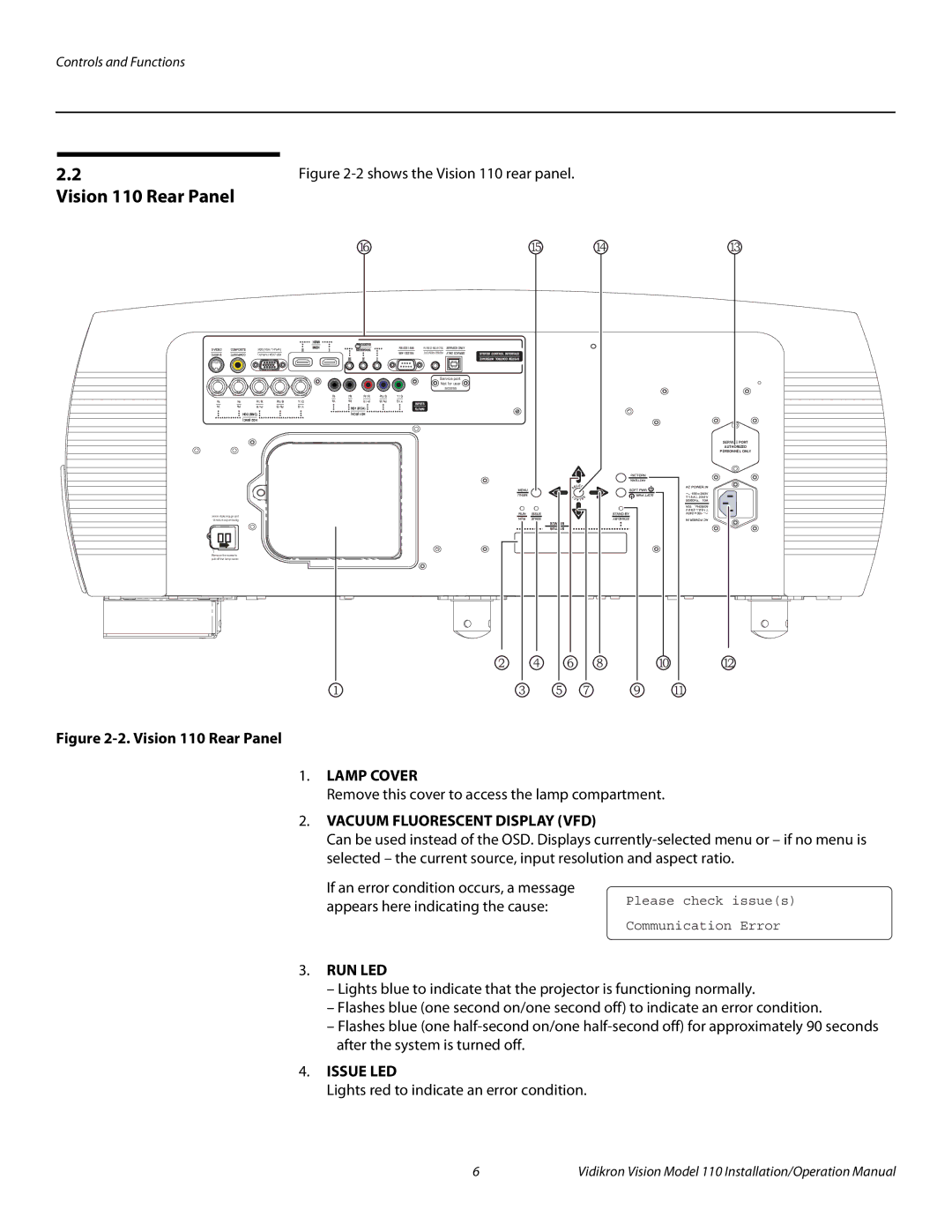
Figure 2-2. Vision 110 Rear Panel
1.LAMP COVER
Remove this cover to access the lamp compartment.
2.VACUUM FLUORESCENT DISPLAY (VFD)
Can be used instead of the OSD. Displays
If an error condition occurs, a message
appears here indicating the cause: | Please check issue(s) |
| |
| Communication Error |
3.RUN LED
–Lights blue to indicate that the projector is functioning normally.
–Flashes blue (one second on/one second off) to indicate an error condition.
–Flashes blue (one
4.ISSUE LED
Lights red to indicate an error condition.
6 | Vidikron Vision Model 110 Installation/Operation Manual |