Installation
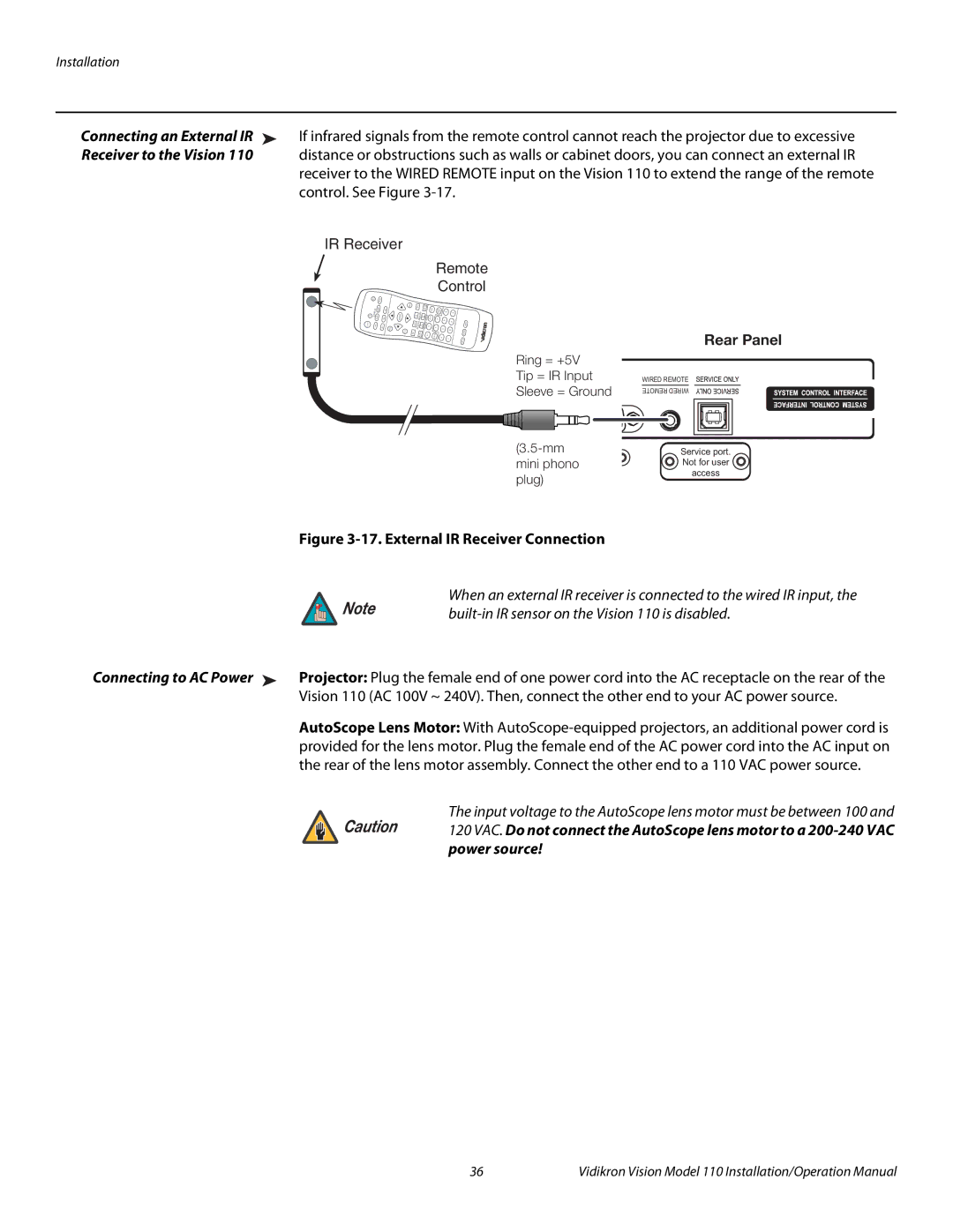
Connecting an External IR ➤ | If infrared signals from the remote control cannot reach the projector due to excessive |
Receiver to the Vision 110 | distance or obstructions such as walls or cabinet doors, you can connect an external IR |
| receiver to the WIRED REMOTE input on the Vision 110 to extend the range of the remote |
| control. See Figure |
| IR Receiver |
| Remote |
| Control |
SOU | RCE |
|
R ENTE
| Y |
| TIO |
PICTURE | RA |
ASPECT |
| 6 | 0 |
2 | 5 | 9 |
|
14 ![]()
8
3 | 7 |
Ring = +5V
Tip = IR Input
Sleeve = Ground
Rear Panel
WIRED REMOTE
REMOTE WIRED
Service port. ![]() Not for user
Not for user ![]() access
access ![]()
Figure 3-17. External IR Receiver Connection
When an external IR receiver is connected to the wired IR input, the
Note | |
|
Connecting to AC Power ➤ Projector: Plug the female end of one power cord into the AC receptacle on the rear of the Vision 110 (AC 100V ~ 240V). Then, connect the other end to your AC power source.
AutoScope Lens Motor: With
Caution | The input voltage to the AutoScope lens motor must be between 100 and |
120 VAC. Do not connect the AutoScope lens motor to a | |
| power source! |
36 | Vidikron Vision Model 110 Installation/Operation Manual |