Controls and Functions
2.3
Vision 110 Rear Connector Panel
10 | 9 | 8 | 7 | 6 | 5 |
|
| HD3 (VGA / |
|
|
|
|
|
|
|
|
| HD1 (RCA) |
HD2 (BNC) | (RCA) HD1 |
(BNC) HD2 |
|
4 | 3 |
WIRED REMOTE |
|
REMOTE WIRED |
|
Service port. ![]() Not for user
Not for user ![]() access
access ![]()
12
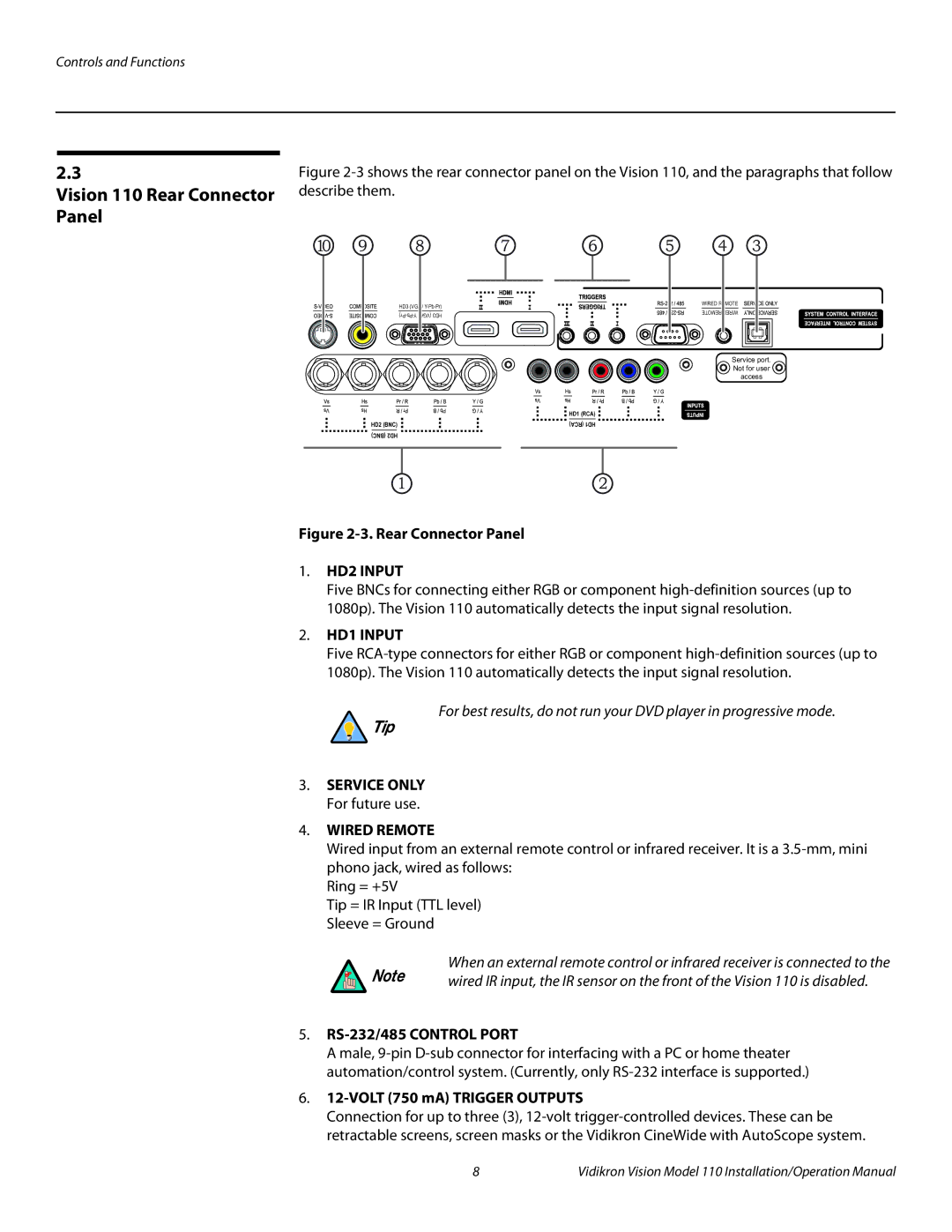
Figure 2-3. Rear Connector Panel
1.HD2 INPUT
Five BNCs for connecting either RGB or component
2.HD1 INPUT
Five
For best results, do not run your DVD player in progressive mode.
Tip
3.SERVICE ONLY For future use.
4.WIRED REMOTE
Wired input from an external remote control or infrared receiver. It is a
Ring = +5V
Tip = IR Input (TTL level) Sleeve = Ground
When an external remote control or infrared receiver is connected to the
Note | wired IR input, the IR sensor on the front of the Vision 110 is disabled. |
|
5.RS-232/485 CONTROL PORT
A male,
6.12-VOLT (750 mA) TRIGGER OUTPUTS
Connection for up to three (3),
8 | Vidikron Vision Model 110 Installation/Operation Manual |