Installation
|
|
|
|
| COMP 1 |
|
|
|
| COMP 2 |
|
|
| ||||
VIDEO | PB/CB | Y | PR/CR | PB/CB | Y | HDMI | |||||||||||
VIDEO | R | C/ | P | B | C/ | P | Y | R | C/ | P | B | C/ | P | Y | HD | HDMI | |
|
| R |
| B |
|
| R |
| B |
|
|
|
| ||||
|
|
|
|
| 1 COMP |
|
|
|
| 2 COMP |
|
|
| ||||
|
|
|
|
|
|
|
|
|
|
|
|
|
|
| |||
|
|
|
|
|
|
|
|
|
|
|
|
|
|
| |||
Personal
Computer
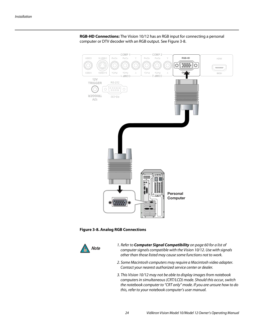
Figure 3-8. Analog RGB Connections
1. Refer to Computer Signal Compatibility on page 60 for a list of
Note | computer signals compatible with the Vision 10/12. Use with signals |
| |
| other than those listed may cause some functions not to work. |
| 2. Some Macintosh computers may require a Macintosh video adapter. |
| Contact your nearest authorized service center or dealer. |
| 3. This Vision 10/12 may not be able to display images from notebook |
| computers in simultaneous (CRT/LCD) mode. Should this occur, switch |
| the notebook computer to “CRT only” mode. If you are unsure how to do |
| this, refer to your notebook computer’s user manual. |
24 | Vidikron Vision Model 10/Model 12 Owner’s Operating Manual |
