General I/O terminal block
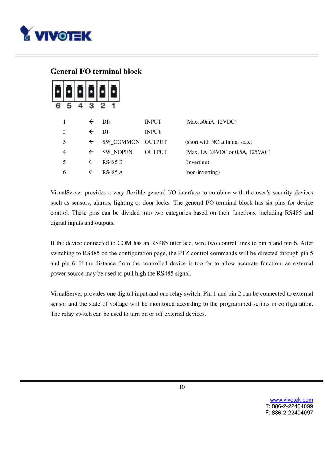
1 | Å | DI+ | INPUT | (Max. 50mA, 12VDC) |
2 | Å | DI- | INPUT |
|
3 | Å | SW_COMMON | OUTPUT | (short with NC at initial state) |
4 | Å | SW_NOPEN | OUTPUT | (Max. 1A, 24VDC or 0.5A, 125VAC) |
5 | Å | RS485 B |
| (inverting) |
6 | Å | RS485 A |
|
VisualServer provides a very flexible general I/O interface to combine with the user’s security devices such as sensors, alarms, lighting or door locks. The general I/O terminal block has six pins for device control. These pins can be divided into two categories based on their functions, including RS485 and digital inputs and outputs.
If the device connected to COM has an RS485 interface, wire two control lines to pin 5 and pin 6. After switching to RS485 on the configuration page, the PTZ control commands will be directed through pin 5 and pin 6. If the distance from the controlled device is too far to allow accurate function, an external power source may be used to pull high the RS485 signal.
VisualServer provides one digital input and one relay switch. Pin 1 and pin 2 can be connected to external sensor and the state of voltage will be monitored according to the programmed scripts in configuration. The relay switch can be used to turn on or off external devices.
10
www.vivotek.com
T: 886-2-22404099
F: