FBB4 OPTIONAL VARIABLE SPEED BLOWER INSTALLATION
Attention: Install blower assembly before connecting gas inlet supply line
Note: Junction box on right side of fireplace must be
1.If installed, turn OFF gas supply to fireplace.
2.If applicable, turn OFF electric supply to fireplace.
3.Lower bottom louver on fireplace.
4.Refer to page 34, "Junction Box Wiring Installation Instructions" to complete wiring of junction box.
Attention: If installed, do not damage gas inlet supply line when blower assembly is inserted into fireplace. If necessary, remove gas inlet supply line.
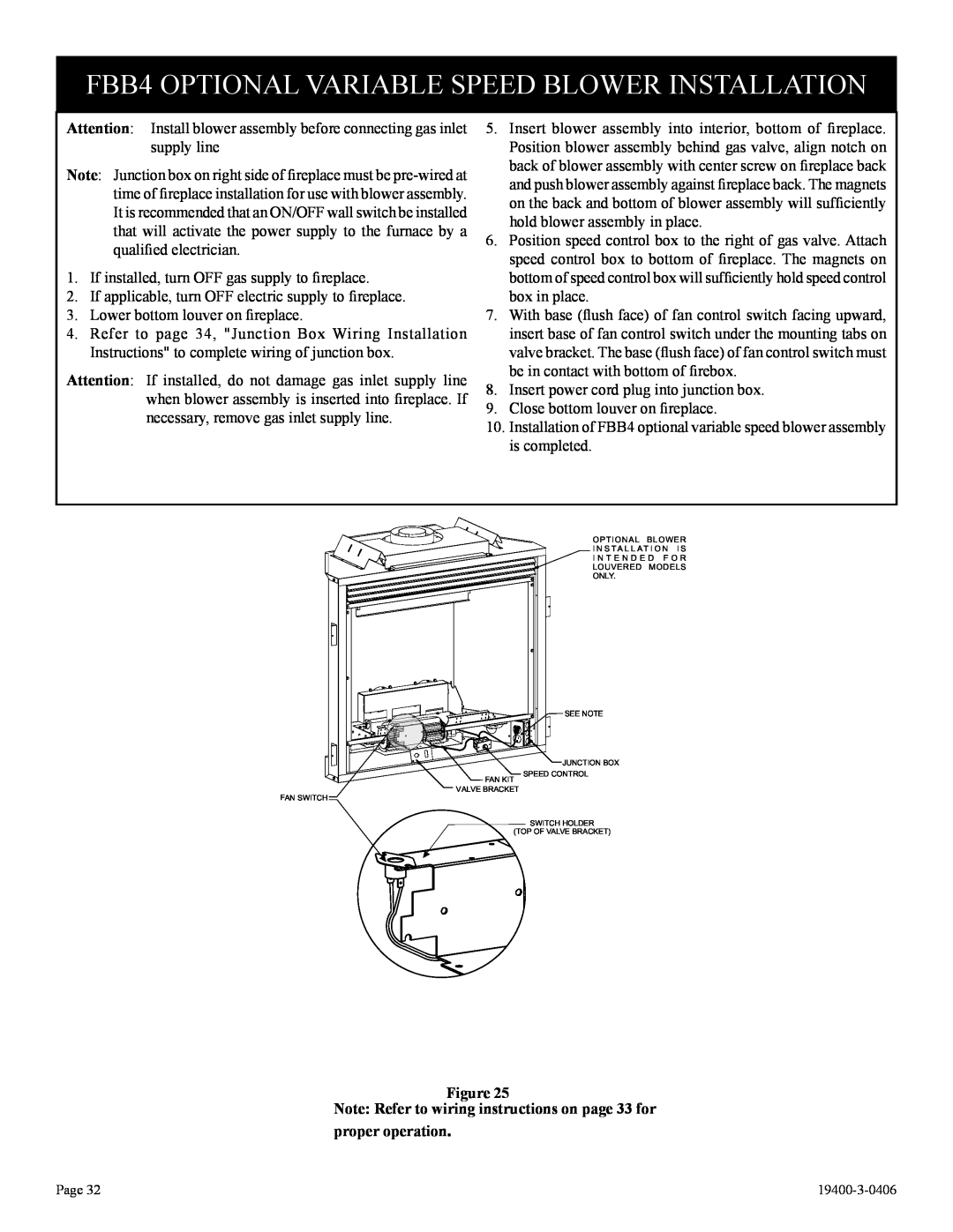
5.Insert blower assembly into interior, bottom of fireplace. Position blower assembly behind gas valve, align notch on back of blower assembly with center screw on fireplace back and push blower assembly against fireplace back. The magnets on the back and bottom of blower assembly will sufficiently hold blower assembly in place.
6.Position speed control box to the right of gas valve. Attach speed control box to bottom of fireplace. The magnets on bottom of speed control box will sufficiently hold speed control box in place.
7.With base (flush face) of fan control switch facing upward, insert base of fan control switch under the mounting tabs on valve bracket. The base (flush face) of fan control switch must be in contact with bottom of firebox.
8.Insert power cord plug into junction box.
9.Close bottom louver on fireplace.
10.Installation of FBB4 optional variable speed blower assembly is completed.
OPTIONAL | BLOWER | |
I N S T A L L A T I O N I S | ||
I N T E N D E D | F O R | |
LOUVERED | MODELS | |
ONLY. |
|
|
| SEE NOTE |
| JUNCTION BOX |
FAN KIT | SPEED CONTROL |
| |
VALVE BRACKET |
|
FAN SWITCH |
|
| SWITCH HOLDER |
(TOP OF VALVE BRACKET) | |
Figure 25
Note: Refer to wiring instructions on page 33 for proper operation.
Page 32 |