Operating Instructions
CONTROL IDENTIFICATION, LOCATION, AND FUNCTION
![]() CAUTION
CAUTION
Before operating the mower, become famil- iar with the location and function of all op- erator controls. Knowing the location, function, and operation of these controls is important for safe and efficient operation of the mower.
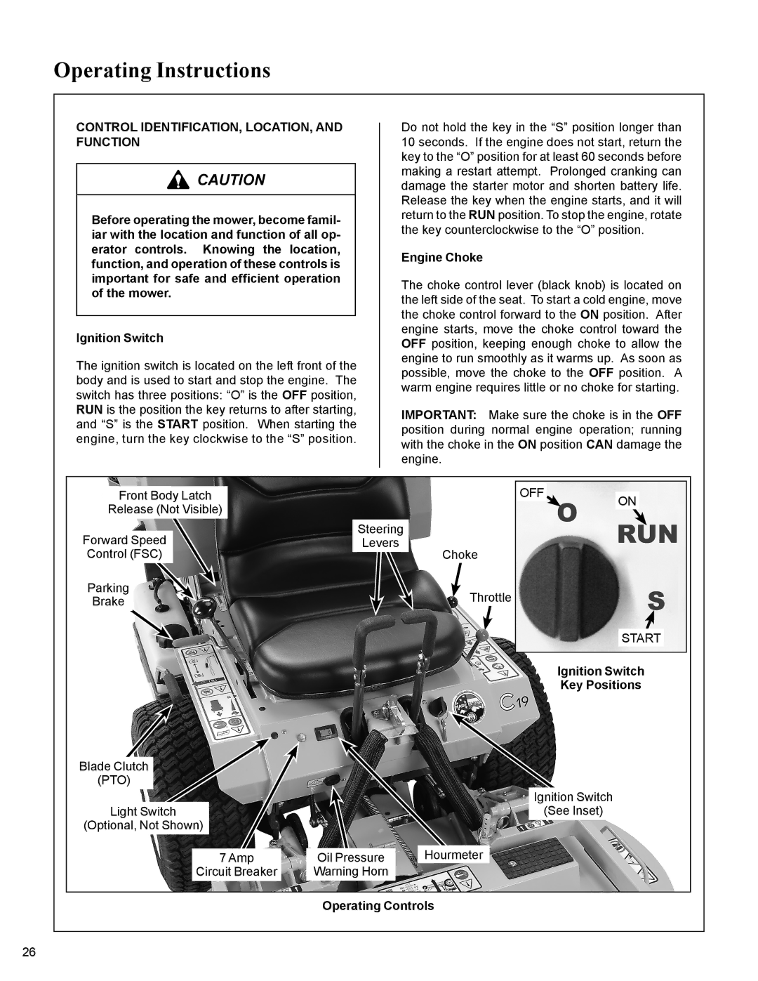
Ignition Switch
The ignition switch is located on the left front of the body and is used to start and stop the engine. The switch has three positions: “O” is the OFF position, RUN is the position the key returns to after starting, and “S” is the START position. When starting the engine, turn the key clockwise to the “S” position.
Do not hold the key in the “S” position longer than 10 seconds. If the engine does not start, return the key to the “O” position for at least 60 seconds before making a restart attempt. Prolonged cranking can damage the starter motor and shorten battery life. Release the key when the engine starts, and it will return to the RUN position. To stop the engine, rotate the key counterclockwise to the “O” position.
Engine Choke
The choke control lever (black knob) is located on the left side of the seat. To start a cold engine, move the choke control forward to the ON position. After engine starts, move the choke control toward the OFF position, keeping enough choke to allow the engine to run smoothly as it warms up. As soon as possible, move the choke to the OFF position. A warm engine requires little or no choke for starting.
IMPORTANT: Make sure the choke is in the OFF position during normal engine operation; running with the choke in the ON position CAN damage the engine.
Front Body Latch |
| OFF | ON |
Release (Not Visible) |
|
| |
|
|
| |
Forward Speed | Steering |
|
|
Levers | Choke |
| |
Control (FSC) |
|
| |
Parking |
| Throttle |
|
Brake |
|
| |
|
|
| START |
|
|
| Ignition Switch |
|
|
| Key Positions |
Blade Clutch |
|
|
|
(PTO) |
|
|
|
|
| Ignition Switch | |
Light Switch |
| (See Inset) | |
(Optional, Not Shown) |
|
|
|
7 Amp | Oil Pressure | Hourmeter |
|
Circuit Breaker | Warning Horn |
|
|
Operating Controls
26