Optional Installation
Door Arm Hookup
Tools: Needle nose pliers
At the center of the top section, measure horizontally from the top of center hinge to the bottom of strut. Using that dimension, measure and cut (2) pieces of perforated angles. Assemble the
(2)pieces together using (2) 3/8” bolts and nuts (supplied by others). Now, secure to the top section using carriage bolts and nuts (supplied by others), thru bolt both the perforated angles to the top section, as shown.
Align the door arm with hole with one of the holes in the perforated angles. Secure the door arm to the perforated angle using (1) 5/16” – 18 x 1” hex head bolt and (1) 5/16” – 18 lock nut (supplied by others), as shown.
Strut |
|
|
|
(2) 3/8” Hex bolt | Top |
| (1) 5/16” Hex bolt |
and lock nut | section | Carriage bolt | and lock nut |
(supplied by others). |
| and nuts | (supplied by others). |
|
| (supplied by |
|
(2) Perforated |
| others) |
|
angles |
|
|
|
|
| Center hinge | Typical |
|
|
| |
|
|
| door arm |
Lift Handles
Tools: Power drill, 1/8” Drill bit, Tape measure
NOTE: Lift handles must be lined up vertically. Bottom Section:
Locate the exterior center stile or center most stile on the bottom section.
NOTE: For flush doors, find the center most stile by locating the center most hinge.
Using the bottom hole of the lift handle, measure up 3” from the bottom of bottom section. Mark the hole locations and drill (2) 9/32” dia. holes through the bottom section. On the outside of the door, insert (2) 1/4” - 20 x 2 1/2” carriage bolts (black head) into the outside lift handle and insert the assembly into the (2)
(2)holes in the inside lift handle over the stems of the carriage bolts. Secure the outside and inside lift handle to the bottom section with (2) 1/4” – 20 flange hex nuts.
Intermediate I Section:
Locate the exterior center stile or center most stile on the Intermediate I section. Mark a vertical line on the section at that point.
NOTE: Some Garage Doors may require both lift handles to be installed on bottom section. If your bottom section height is 28” or 29”, install both lift handles onto the bottom section. Install bottom lift handle per above instructions, then install the second lift handle a Minimum of 20” and a Maximum of 30” above the bottom lift handle.
Measure up 4” from the bottom of the Intermediate I section. Using this measurement as a guide, position the bottom hole of the lift handle bottom at the mark. Make a mark at the top hole of the lift handle. This should give you a Minimum of 20” and a Maximum of 30” between the lower lift handle and the middle of the top lift handle. If needed, reposition the lift handle to stay within the Minimum and Maximum dimensions, as stated above.
Using the lift handle as a template, mark the hole locations and drill (2) 9/32” dia. holes through the section. On the outside of the door, insert (2) 1/4” - 20 x 2 1/2” carriage bolts (black head) into the outside lift handle and insert the assembly into the (2)
| Lift | (2) 1/4” - 20 x 2 1/2” |
| Carriage bolts and (2) 1/4” – 20 | |
Intermediate I | handle | Flange hex nuts |
|
| |
section |
|
|
|
| Center |
Bottom |
| hinge |
Lift |
| |
section | (2) 1/4” - 20 x 2 1/2” | |
| handle | |
|
| Carriage bolts and (2) 1/4” – 20 |
Strut |
| Flange hex nuts |
| 3” |
|
Pull Down Rope
Tools: Power drill, 1/8” Drill bit, Tape measure
![]() WARNING
WARNING
Do not install pull down rope on doors with operators. Children may become entangled in the rope causing severe or fatal injury.
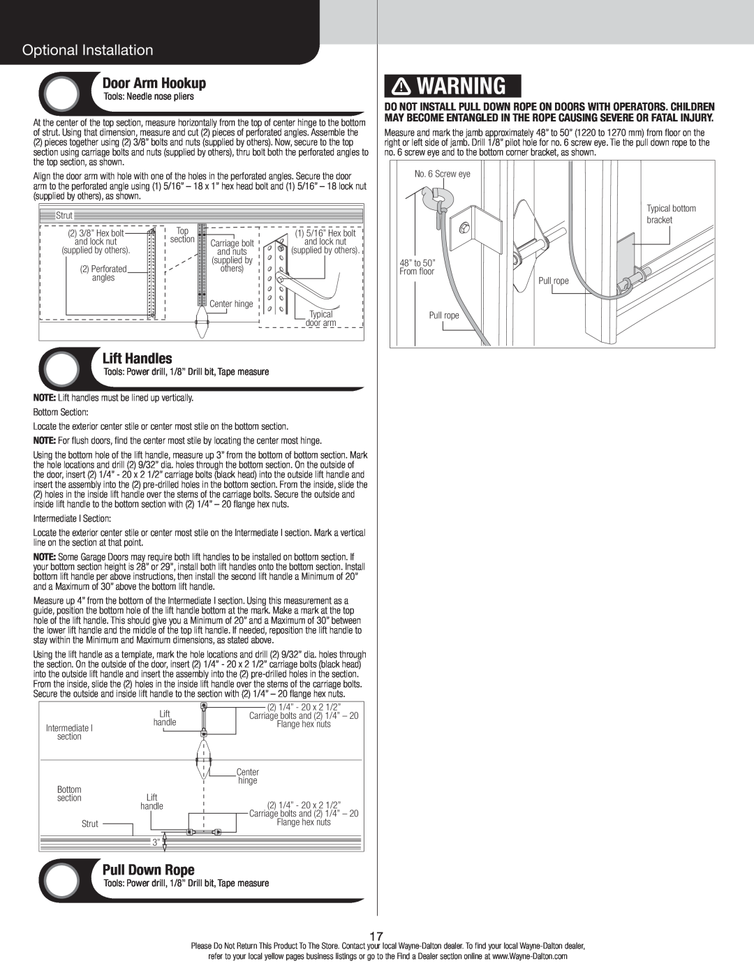
Measure and mark the jamb approximately 48” to 50” (1220 to 1270 mm) from floor on the right or left side of jamb. Drill 1/8” pilot hole for no. 6 screw eye. Tie the pull down rope to the no. 6 screw eye and to the bottom corner bracket, as shown.
No. 6 Screw eye |
Typical bottom |
bracket |
48” to 50” |
From floor |
Pull rope |
Pull rope |
17
Please Do Not Return This Product To The Store. Contact your local
refer to your local yellow pages business listings or go to the Find a Dealer section online at