Page 11
1.4REAR PANEL CONNECTIONS
The DVR395 rear panel connections are shown and described in Figure 2 (Page13).
RF IN
| AUDIO |
| AUDIO |
| 2 |
| 1 |
|
|
| MODE |
R | L | R | L |
|
|
|
|
|
|
| S/N |
|
SERIAL | ALARM | CLOSURE | VIDEO | |||||
| PORT | N/O COM GND | 1 |
| 2 |
| ||
|
|
|
|
| ||||
|
| N/C + | - | + | - |
|
| |
|
|
|
|
|
|
| ||
1 | 6 | CONTACT RATING 0.1A @ 30VDC | OUT | OUT | ||||
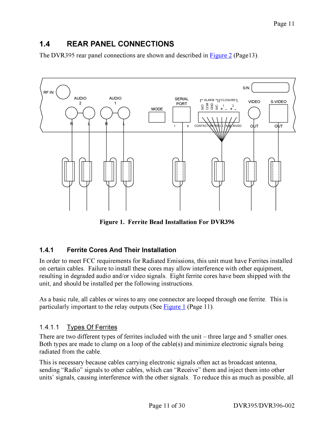
Figure 1. Ferrite Bead Installation For DVR396
1.4.1Ferrite Cores And Their Installation
In order to meet FCC requirements for Radiated Emissions, this unit must have Ferrites installed on certain cables. Failure to install these cores may allow interference with other equipment, resulting in degraded audio and/or video signals. Eight ferrite cores have been shipped with the unit, and should be installed per the following instructions.
As a basic rule, all cables or wires to any one connector are looped through one ferrite. This is particularly important to the relay outputs (See Figure 1 (Page 11).
1.4.1.1Types Of Ferrites
There are two different types of ferrites included with the unit – three large and 5 smaller ones. Both types are made to clamp on a loop of the cable(s) and minimize electronic signals being radiated from the cable.
This is necessary because cables carrying electronic signals often act as broadcast antenna, sending “Radio” signals to other cables, which can “Receive” them and inject them into other units’ signals, causing interference with the other signals. To reduce this as much as possible, all
Page 11 of 30 |