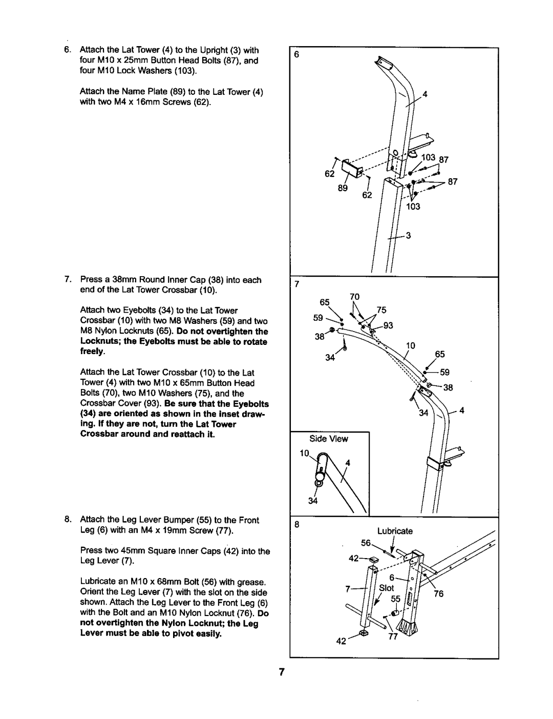
6.Attach the Lat Tower (4) to the Upright (3) with four M10 x 25mm Button Head Bolts (87), and four M19 Lock Washers (103).
Attach the Name Plate (89) to the Lat Tower (4) with t_o M4 x 16mm Screws (62).
62 _. | °° | : |
103
7. Press a 38mm Round Inner Cap (38) into each |
| |
end of the Lat Tower Crossbar (10). | 70 | |
| ||
| 65 | |
Attach two Eyebolts (34) to the Lat Tower | 75 | |
59 | ||
Crossbar (10) with two M8 Washers (59) and two | ||
| ||
M8 Nylon Locknuts (65). Do not overtighten the |
| |
Loeknuts; the Eyebolts must be able to rotate | 10 | |
freely. | 65 |
Attach the Lat Tower Crossbar (10) to the Lat
Tower (4) with two M10 x 65mm Button Head
Bolts(70), two M10 Washers (75), and the
Crossbar Cover (93). Be sure that the Eyebolts
(34)are oriented as shown in the inset drew- ing. If they are not, turn the Lat Tower
Crossbar around and reattach it. | Side View |
|
8. Attach the Leg Lever Bumper (55) to the Front | 8 |
Leg (6) with an M4 x 19mm Screw (77). | Lubricate |
| |
Press two 45mm Square Inner Caps (42) into the |
|
Leg Lever (7). |
|
Lubricate an M10 x 68mm Bolt (56) with grease. | 76 |
Orient the Leg Lever (7) with the slot on the side | |
shown. Attach the Leg Lever to the Front Leg (6) |
|
with the Bolt and an M10 Nylon Locknut (76). Do not overtighten the Nylon Locknut; the Leg Lever must be able to pivot easily.
42
7
