ASSEMBLY
Make Thk'tg=F.al_r for Youmeif
TNsm_ual _s€_ned.to_ thatmerest-
ante_ canhe'assembled by
most people, However, it I_,i_= ntt0 reallz8 that the versatile re,stance system has r_ny
partsandtt_t'theas_ pro=='_lltake
UmeM._t _op_ _ _at W s6_ngask_pk_ty of_. assemUy g0_=_t_y.
Before beginning assembly, carefully read the following information and instructions:
•Assembly requires two persons.
•Place all parts m a cleared area and remove the packing materials. Do not d_sposeof the packing materials until assembly is completed.
•For help identifying small parts, use the PART IDENTIFICATION CHART. Note: Some small
parts may have been
•Tighten all parts as you assemble them. unless instructedto do otherwise.
•As you assemble the resistance system, make sure all parts are odented as shown in the draw- ings
The included IAIlen wrenche.e.e.ande.e.ethe. .efollow.e- ing tools (not included) are required for assam- bly:
•Two adjustable wrenches
•One rubber mallet
•One standard screwddver
•One Phillips screwdriver
•Lubricant, such as grease or petroleum jelly, and soapy water.
Assembly will be more convenient if you have a socket set, a set of
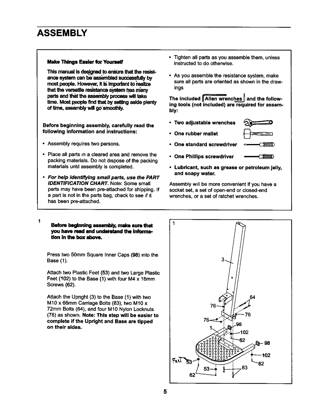
Befo_ l=_=Nng a=._bly, make=am that 1
you hayedraad =nd nmda_,_tand _ lion In lIND_
Press two 50mm Square Inner Caps (98) into the
Base (1).
Attach two Plastic Feet (53) and two Large Plastic Feet (102) to the Base (1) w=thfour M4 x 16mm
Screws (62).
Attach the Upnght (3) to the Base (1) with two M10 x 66ram Carriage Bolts (83), two M1O x 72mm Bolts (64). and four M10 Nylon Locknuts (76) as shown. Note: This step will be easier to
complete if the Updght and Base are tipped on their sides.
3
64
76
o_,_," 76
J 63 | L62 |
5